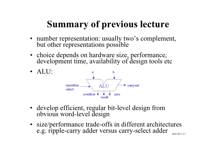

Summary of previous lecture • number representation: usually two’s complement, but other representations possible • choice depends on hardware size, performance, development time, availability of design tools etc • ALU: • develop efficient, regular bit-level design from obvious word-level design • size/performance trade-offs in different architectures e.g. ripple-carry adder versus carry-select adder dt10 2011 5.1
Datapath and control: 3-step derivation (3 rd Ed: p.284-314, 4 th Ed: p.300-330) • separate datapaths for: – register-based instructions e.g. add, sub – memory-access instructions e.g. lw, sw – branch instructions e.g. beq, j • combined datapath for all instructions – add multiplexors • use correct part for each instruction – control signals for multiplexors + ALU dt10 2011 5.2
Register-based instructions • select read/write registers from operands • select ALU operation from opcode and function field • add $5, $6, $7 # reg[5] = reg[6] + reg[7] dt10 2011 5.3
Memory access instructions: load • lw $5, offset($6) # reg[5] = M[reg[6] + offset] assume data memory to return value in same cycle dt10 2011 5.4
Memory access instructions: store • sw $5, offset($6) # M[reg[6] + offset] = reg[5] dt10 2011 5.5
Combine datapaths for R-type and memory instructions: R-type flow • 1 register file, 1 ALU • ALU input mux: data from register or instruction • register write mux: data from ALU or memory dt10 2011 5.6
Combine datapaths for R-type and memory instructions: memory flow • 1 register file, 1 ALU • ALU input mux: data from register or instruction • register write mux: data from ALU or memory dt10 2011 5.7
Branch instructions • beq $5, $6, L dt10 2011 5.8
Combined datapath: without instruction memory dt10 2011 5.9
Combined datapath: with instruction memory dt10 2011 5.10
Combined datapath for R-type dt10 2011 5.11
Combined datapath for load dt10 2011 5.12
Combined datapath for branch dt10 2011 5.13
ALUOp (from control unit) ALU ALU control ALU function control control code input • from opcode and fn code, determine ALU control constant lecture on ALU from opcode specify instruction type dt10 2011 5.14
ALU control: optimisation insert don’t cares (Xs) since 11 never arises • K-map for rightmost bit: F0 or F3 • combine ALUOp: ALUOp1 and (F0 or F3) dt10 2011 5.15
Identify control signals • ALU: ALUOp • control 4 mux: RegDst, ALUSrc, MemtoReg, PCSrc • storage: Register Write, Memory Read/Write dt10 2011 5.16
Control signal summary dt10 2011 5.17
R-type instruction (1) dt10 2011 5.18
R-type instruction (2) dt10 2011 5.19
R-type instruction (3) dt10 2011 5.20
R-type instruction (4) dt10 2011 5.21
Load instruction (1) dt10 2011 5.22
Load instruction (2) dt10 2011 5.23
Load instruction (3) dt10 2011 5.24
Load instruction (4) and (5) dt10 2011 5.25
Branch instruction (1) dt10 2011 5.26
Branch instruction (2) dt10 2011 5.27
Control unit for single-cycle datapath • combinational circuit: no registers • 6-bit opcode input e.g. lw 100011 (35 ten ) • 9-bit output, control mux, ALU, read/write op • e.g. lw: mux memory/register ALU ------ -------------------- ------ RegDst = 0 MemRead = 1 ALUOp = 0 Branch = 0 MemWrite = 0 MemtoReg = 1 RegWrite = 1 ALUSrc = 1 dt10 2011 5.28
Load instruction (1) • lw $5,offset($6) dt10 2011 5.29
Load instruction (2) • lw $5,offset($6) dt10 2011 5.30
Load instruction (3) • lw $5,offset($6) dt10 2011 5.31
Load instruction (4) and (5) • lw $5,offset($6) dt10 2011 5.32
Recommend
More recommend