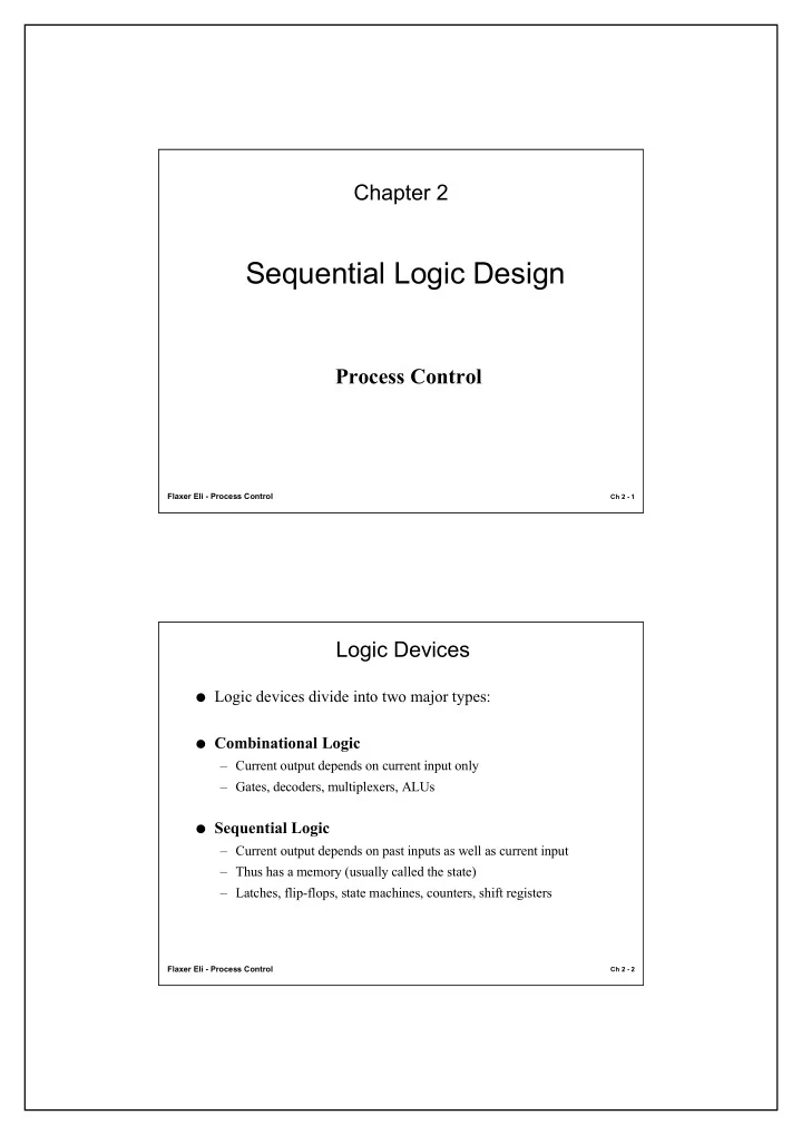

Chapter 2 Sequential Logic Design Process Control Flaxer Eli - Process Control Ch 2 - 1 Logic Devices ● Logic devices divide into two major types: ● Combinational Logic – Current output depends on current input only – Gates, decoders, multiplexers, ALUs ● Sequential Logic – Current output depends on past inputs as well as current input – Thus has a memory (usually called the state) – Latches, flip-flops, state machines, counters, shift registers Flaxer Eli - Process Control Ch 2 - 2
Sequential Logic Definitions ● Clock - the master timing element behind the state changes of most sequential circuits. – a clock signal is active high if the state changes occur at the rising edge – and active low if state changes occur at the falling edge. ● Clock Period - time between successive transitions in the same direction. ● Clock Frequency - reciprocal of the clock period. ● Duty Cycle - the percentage of time that a clock is at its assertion level. Flaxer Eli - Process Control Ch 2 - 3 Clock Characteristics State change Frequency = 1/Period Active t L t H Duty Cycle High = t H /Period Period State change Active t L Duty Cycle t H = t L /Period Low Period Flaxer Eli - Process Control Ch 2 - 4
What Are Latches and Flip-flops? ● Common feedback sequential circuits ● Latch – Single-bit storage (memory) – Changes state at any time due to input change ● Flip-flop – Also single-bit storage – Changes state ONLY when a clock edge or pulse is applied Flaxer Eli - Process Control Ch 2 - 5 Types of Latches and Flip-flops ● Latches – S-R Latch – S-R Latch with Enable – D Latch ● Flip-flops – Edge-Triggered D Flip-Flop – Edge-Triggered S-R Flip-Flop – Edge-Triggered J-K Flip-Flop – T Flip-Flop Flaxer Eli - Process Control Ch 2 - 6
S-R Latch Function Table Symbol S R Q /Q Set Q a S Q 0 0 Last Q Last /Q Hold 0 1 0 1 Reset Reset R Q /Q a 1 0 1 0 Set 0 0 1 1 ILLEGAL Schematic R Q Consider: Timing Diagram Propagation delay /Q S Minimum pulse width Oscillation Flaxer Eli - Process Control Ch 2 - 7 D Flip-Flop C D Q /Q D Q 1 0 0 1 C Q 1 0 1 1 Last Q Last /Q 0 X Q D S C Store a data bit, not set/reset C “Transparent latch” R Q No illegal operation problem Setup and Hold time D Q C /Q Flaxer Eli - Process Control Ch 2 - 8
Positive-Edge-Triggered D Flip-Flop D Q D CLK Q /Q 0 0 1 >CLK Q 1 0 1 Last Q Last /Q X 0 Last Q Last /Q X 1 S Q B S R Q Q S Q R R Q Q’ S Q C C = 0 C = 1 D R Q A D = 0 D = 1 D = 0 D = 1 B 0 1 0 1 S 1 1 1 0 R 1 1 0 1 A 1 0 1 0 Q N .C. N .C. 0 1 Q’ N .C. N .C. 1 0 Flaxer Eli - Process Control Ch 2 - 9 Negative-Edge-Triggered D Flip-Flop D CLK Q /Q 0 0 1 D Q 1 0 1 Last Q Last /Q X 0 >CLK Q Last Q Last /Q X 1 Flaxer Eli - Process Control Ch 2 - 10
Edge-Triggered J-K Flip-Flop C Q /Q J K X X 0 Last Q Last /Q J Q Last Q Last /Q X X 1 >CLK Last Q Last /Q 0 0 K Q 0 1 0 1 1 0 1 0 Last /Q Last Q 1 1 J Q D Q K >CLK Q /Q CLK Flaxer Eli - Process Control Ch 2 - 11 T (toggle) Flip-Flop ● A T flip-flop changes state on every clock tick. ● Possible circuit designs – T without enable 1 Q Q J Q D Q C >CLK K Q /Q C >CLK Q /Q T CLK Q / Q T with enable 0 Q /Q T Q J Q 1 /Q Q C >CLK 0 X Q /Q K Q /Q 1 X Q /Q Flaxer Eli - Process Control Ch 2 - 12
Flip-Flop D F.F. SR F.F. D Q S Q >CLK >CLK Q R Q T F.F. JK F.F. T Q J Q >CLK >CLK Q K Q Flaxer Eli - Process Control Ch 2 - 13
Recommend
More recommend