
Combinational Logic (II) Prof. Usagi Recap: Combinational v.s. - PowerPoint PPT Presentation
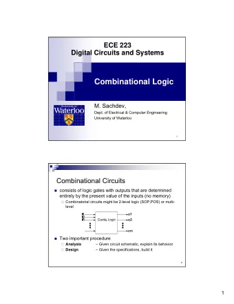
Combinational Logic (II) Prof. Usagi Recap: Combinational v.s. sequential logic Combinational logic The output is a pure function of its current inputs The output doesnt change regardless how many times the logic is triggered
Combinational Logic (II) Prof. Usagi
Recap: Combinational v.s. sequential logic • Combinational logic • The output is a pure function of its current inputs • The output doesn’t change regardless how many times the logic is triggered — Idempotent • Sequential logic • The output depends on current inputs, previous inputs, their history 2
Recap: Basic Boolean Algebra Concepts • {0, 1}: The only two possible values in inputs/outputs • Basic operators • AND (•) — a • b • returns 1 only if both a and b are 1s • otherwise returns 0 • OR (+) — a + b • returns 1 if a or b is 1 • returns 0 if none of them are 1s • NOT (‘) — a’ • returns 0 if a is 1 • returns 1 if a is 0 3
Recap: Definitions of Boolean Function Expressions • Complement: variable with a bar over it or a ‘ — A’, B’, C’ • Literal: variable or its complement — A, A’, B, B’, C, C’ • Implicant (Product term): product of literals — ABC, AC, BC • Implicate (Sum terms): sum of literals — (A+B+C), (A+C), (B+C) • Minterm: AND that includes all input variables — ABC, A’BC, AB’C • Maxterm: OR that includes all input variables — (A+B+C), (A’+B+C), (A’+B’+C) 4
Recap: Boolean operators their circuit “gate” symbols AND NAND OR NOR XOR NOT represents where we take a compliment value on an input NXOR represents where we take a compliment value on an output 5
How to express y = e(ab+cd) # inputs : 5 AND # outputs : 1 a # gates : 4 OR b # signal nets : 9 NOT # pins: 12 c NAND d NOR y XOR e NXOR 6
Recap: You can also use only NANDs Inverter Inverter Now, only 5 gates and 4 transistors each — 20 transistors! a b c y d Inverter Inverter e 7
Recap: Canonical form — Sum of “Minterms” Input Output A minterm X Y 0 0 0 f(X,Y) = XY’ + XY Sum (OR) of “minterms” 0 1 0 1 0 1 1 1 1 XNOR Input Output f(A,B) = A’B’ + AB A B 0 0 1 0 1 0 1 0 0 1 1 1 8
Outline • Let’s start designing the first circuit • Designing circuit with HDL • Let’s optimize the circuit! 9
Canonical form — Product of “Maxterms” A “maxterm Input Output f(X,Y) = (X+Y) (X + Y’) Product of maxterms X Y 0 0 0 0 1 0 1 0 1 1 1 1 XNOR Input Output A B f(A,B) = (A+B’) (A’+B) 0 0 1 0 1 0 1 0 0 1 1 1 10
Sum-of-minterms/product-of-maxterms • They can be used interchangeably • Depends on if the truth table has more 0s or 1s in the result • Neither forms give you the “optimized” equation. By optimized, we mean — minimize the number of operations 11
Let’s design a circuit! 12
Binary addition 3 + 2 = 5 3 + 3 = 6 1 carry 1 1 0 0 1 1 0 0 1 1 + 0 0 1 0 + 0 0 1 1 0 0 1 0 1 1 1 0 half adder — adder Input Output without a carry as an input full adder — adder with A B Cin Out Cout a carry as an input Input Output 0 0 0 0 0 0 1 0 1 0 A B Out Cout 1 0 0 1 0 0 0 0 0 1 1 0 0 1 0 1 1 0 0 0 1 1 0 1 0 1 0 0 1 1 0 1 1 1 0 1 1 0 1 0 1 1 1 1 1 1 13
Binary addition Inputs — two 4-bit binary numbers: A 3 A 2 A 1 A 0 A 0 B 0 A 2 B 2 A 1 B 1 A 3 B 3 B 3 B 2 B 1 B 0 Output — one 4-bit Full Half Full Full binary number C 1 Adder Adder Adder C 0 Adder C 3 C 2 O 3 O 2 O 1 O 0 O 3 O 2 O 1 O 0 14
Half adder Out = A’B + AB’ Input Output Cout = AB A B Out Cout 0 0 0 0 A 0 1 1 0 1 0 1 0 Out 1 1 0 1 B Cout 15
Poll close in The sum-of-product form of the full adder • How many of the following minterms are part of the sum-of-product form of the full adder in generating the output bit? ① A’B’Cin’ ② A’BCin’ ③ AB’Cin’ ④ ABCin’ ⑤ A’B’Cin ⑥ A’BCin ⑦ AB’Cin ⑧ ABCin A. 0 B. 1 C. 2 D. 3 E. 4 16
The sum-of-product form of the full adder • How many of the following minterms are part of the sum-of-product form of the full adder in generating the output bit? ① A’B’Cin’ Input Output ② A’BCin’ Out = A’BCin’ + AB’Cin’ + A’B’Cin + ABCin A B Cin Out Cout ③ AB’Cin’ Cout = ABCin’ + A’BCin + AB’Cin + ABCin 0 0 0 0 0 ④ ABCin’ 0 1 0 1 0 ⑤ A’B’Cin ⑥ A’BCin 1 0 0 1 0 ⑦ AB’Cin 1 1 0 0 1 ⑧ ABCin 0 0 1 1 0 A. 0 0 1 1 0 1 B. 1 1 0 1 0 1 C. 2 1 1 1 1 1 D. 3 E. 4 17
Out = A’BCin’ + AB’Cin’ + A’B’Cin + ABCin Cout = ABCin’ + A’BCin + AB’Cin + ABCin The same The full adder Input Output A B Cin Out Cout 0 0 0 0 0 A 0 1 0 1 0 Out 1 0 0 1 0 1 1 0 0 1 0 0 1 1 0 0 1 1 0 1 B 1 0 1 0 1 1 1 1 1 1 Cin Cout 18
Do we need to perform hardware design in gate-level? — Not when you can use an HDL! 19
Turn a design into Verilog 20
Verilog • Verilog is a Hardware Description Language (HDL) • Used to describe & model the operation of digital circuits. • Specify simulation procedure for the circuit and check its response — simulation requires a logic simulator. • Synthesis: transformation of the HDL description into a physical implementation (transistors, gates) • When a human does this, it is called logic design. • When a machine does this, it is called synthesis. • In this class, we use Verilog to implement and verify your processor. • C/Java like syntax 21
Data types in Verilog • Bit vector is the only data type in Verilog • A bit can be one of the following • 0: logic zero • 1: logic one • X: unknown logic value, don’t care • Z: high impedance, floating • Bit vectors expressed in multiple ways • 4-bit binary: 4‘b11_10 ( _ is just for readability) • 16-bit hex: 16‘h034f • 32-bit decimal: 32‘d270 22
Operators Arithmetic Logical Bitwise Relational + addition ! not ~ not > greater than - substraction && and & and < less than * multiplication || or | or >= greater or equal / division ^ xor <= less or equal Don’t use % modulus ~^ xnor == equal (doesn’t work if there is x, z) ** power << shift left != not equal >> shift right === really equal Concatenation {} (e.g., {1b’1,1b’0} is 2b’10) Replication {{}} (e.g., {4{1b’0}} is 4b’0) Conditional condition ? value_if_true : value_if_false 23
Wire and Reg • wire is used to denote a hardware net — “continuously assigned” values and do not store • single wire wire my_wire; • array of wires wire[7 : 0] my_wire; • reg is used for procedural assignments — values that store information until the next value assignment is made. • again, can either have a single reg or an array reg[7 : 0] result; // 8-bit reg • reg is not necessarily a hardware register • you may consider it as a variable in C 24
Revisit the 4-bit adder A 0 B 0 A 2 B 2 A 1 B 1 A 3 B 3 reg, reg, reg, reg, reg, reg, reg, reg, input input input input input input input input reg, reg, reg, reg, reg, reg, reg, Full Half Full Full output output output output input input input C 1 Adder Adder Adder C 0 Adder C 3 C 2 Module Module Module Module reg, reg, reg, reg, O 3 O 2 O 1 O 0 output output output output 25
Half adder Out = A’B + AB’ Input Output Cout = AB A B Out Cout 0 0 0 0 0 1 1 0 module HA( input a, Input ports 1 0 1 0 input b, 1 1 0 1 output cout, Output ports output out ); assign out = (~a & b)|(a & ~b); assign cout = a&b; endmodule 26
Full adder Out = A’BCin’ + AB’Cin’ + A’B’Cin + ABCin Cout = ABCin’ + A’BCin + AB’Cin + ABCin Input Output A B Cin Out Cout 0 0 0 0 0 module FA( input a, 0 1 0 1 0 input b, 1 0 0 1 0 input cin, output cout, 1 1 0 0 1 output out ); 0 0 1 1 0 assign out = (~a&b&~cin)|(a&~b&~cin)|(~a&~b&cin)|(a&b&cin); 0 1 1 0 1 assign cout = (a&b&~cin)|(~a&b&cin)|(a&~b&cin)|(a&b&cin);; endmodule 1 0 1 0 1 1 1 1 1 1 27
The Adder module FA( input a, input b, input cin, output cout, output out ); assign out = (~a&b&~cin)|(a&~b&~cin)|(~a&~b&cin)|(a&b&cin); assign cout = (a&b&~cin)|(~a&b&cin)|(a&~b&cin)|(a&b&cin);; endmodule module HA( input a, input b, output cout, output out ); assign out = (~a & b)|(a & ~b); assign cout = a&b; endmodule module adder( input[3:0] A, input[3:0] B, Connecting ports by name yields output[3:0] O, clearer and less buggy code. output cout); wire [2:0] carries; HA ha0(.a(A[0]), .b(B[0]), .out(O[0]), .cout(carries[0])); FA fa1(.a(A[1]), .b(B[1]), .cin(carries[0]), .out(O[1]), .cout(carries[1])); FA fa2(.a(A[2]), .b(B[2]), .cin(carries[1]), .out(O[2]), .cout(carries[2])); FA fa3(.a(A[3]), .b(B[3]), .cin(carries[2]), .out(O[2]), .cout(cout); endmodule 28
Always block — combinational logic • Executes when the condition in the sensitivity list occurs module FA( input a, input b, input cin, output cout, output out ); always@(a or b or cin) begin // the following block changes outputs when a, b or cin changes assign out = (~a&b&~cin)|(a&~b&~cin)|(~a&~b&cin)|(a&b&cin); assign cout = (a&b&~cin)|(~a&b&cin)|(a&~b&cin)|(a&b&cin);; end endmodule 29
Recommend


More recommend
Explore More Topics
Stay informed with curated content and fresh updates.