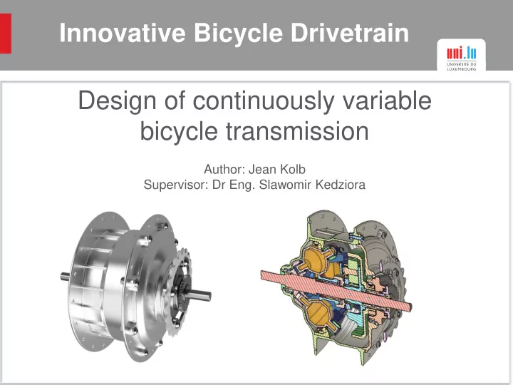

Innovative Bicycle Drivetrain Design of continuously variable bicycle transmission Author: Jean Kolb Supervisor: Dr Eng. Slawomir Kedziora
Chain drive with derailleur change mechanism 98.5% efficiency Relatively low weight The most common drivetrain Not innovative
NuVinci CVT hub Continuously variable ratio Torque transmitted by traction Ball planets change the contact angle Source: https://www.fallbrooktech.com/nuvinci-technology
CVT hub by Hiroyuki Urabe Used as reference for own design Upstream planetary gear train and roller train Estimated efficiency of 90% Patented, but not developed
CVT hub by Hiroyuki Urabe Pros Cons Different and innovative Relatively heavy weight Continuously variable Lower transmission efficiency Enhanced e-bike engine More complex than the efficiency comparable design from “ NuVinci ” Protected in hub enclosure Clean look
Presentation and explanation of the developed design CVT hub
Developed CVT hub Autodesk Fusion 360 unites every development step Cloud computing
Developed CVT hub
Developed CVT hub Upstream planetary gear train Input Output Sprocket Input Input torque on ring gear Fixed carrier
Developed CVT hub Planetary roller train Output Input Input torque on sun roller Non-rotatable but on axle displaceable carrier
Preloaded spring Preloaded spring to guarantee enough traction Wave spring
Preloaded spring Spline Needle bearings Radial bearing on slidable sleeve Axial bearing gets pushed Left handed thread Gap between roller and sun Left handed thread
Changing the ratio Control sleeve gets rotated Spiral groove Rod slides in guideway Roller carrier attached on rod Control sleeve Roller carrier Rod
Ratio range Crank set to rear sprocket -> 0.5 Planetary gear train (Step 1) -> 0.37 Low ratio High ratio Planetary gear train (Step 2) -> 1.82 Planetary roller train -> 1.5 to 6 (Ratio) 12.95 (Roller carrier displacement in mm) Lowest ratio = 0.5 400% ratio range Highest ratio = 2
Input power and standard dimensions 75 W at 60 rpm for 30 minutes 12 Nm input torque Maximum peak 200 W 75 W Standard dimensions: Over-locknut-dimension : 135 mm Axle threads on both sides: M10 x 1 Flange width : 3.2 mm Source: Bicycling Science, Second Edition 2nd Edition, Frank Rowland Whitt, David Gordon Wilson, Number of spoke holes : 36 ISBN-10: 026273060X
Finite Elements Analysis FEA Examples
FEA Static linear analysis Reaction forces have been calculated Parabolic mesh – second order tetra element Fusion cloud computing Analysed components: Roller planet Roller ring Axle Sprocket-ring gear assembly Control sleeve (part 1) Roller sun Control sleeve (part 2) Roller carrier Gear carrier Enclosure
FEA example: Gear carrier Aluminium 201.0-T6 Casting Alloy Yield strength : 435 MPa Fatigue strength : 135 MPa Maximal principal stress : 83.8 MPa
FEA example: Gear carrier 0.022 mm displacement on planet gear location
FEA example: Enclosure Analysed with ANSYS software Wheel assembly with pretension spokes, rim and tire Aluminium 201.0-T6 Casting Alloy
FEA example: Enclosure
Conclusion 400% ratio range N360: 360% (NuVinci CVT) 2.7 kg weight N360: 2.45 kg Difficulties: Limited space for the design Further work: Selection of the right lubrication Simplification of certain components Weight reduction Fatigue analysis
Recommend
More recommend