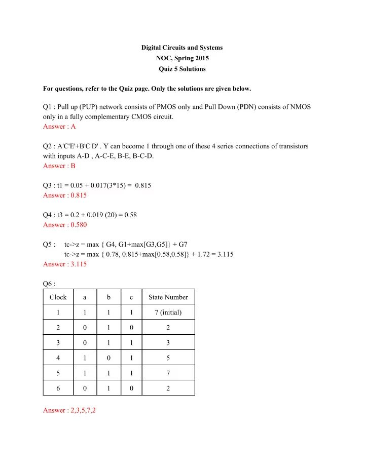

Digital Circuits and Systems NOC, Spring 2015 Quiz 5 Solutions For questions, refer to the Quiz page. Only the solutions are given below. Q1 : Pull up (PUP) network consists of PMOS only and Pull Down (PDN) consists of NMOS only in a fully complementary CMOS circuit. Answer : A Q2 : A'C'E'+B'C'D' . Y can become 1 through one of these 4 series connections of transistors with inputs AD , ACE, BE, BCD. Answer : B Q3 : t1 = 0.05 + 0.017(3*15) = 0.815 Answer : 0.815 Q4 : t3 = 0.2 + 0.019 (20) = 0.58 Answer : 0.580 Q5 : tc>z = max { G4, G1+max[G3,G5]} + G7 tc>z = max { 0.78, 0.815+max[0.58,0.58]} + 1.72 = 3.115 Answer : 3.115 Q6 : Clock a b c State Number 1 1 1 1 7 (initial) 2 0 1 0 2 3 0 1 1 3 4 1 0 1 5 5 1 1 1 7 6 0 1 0 2 Answer : 2,3,5,7,2
Q7 : When start signal is given in the first clock cycle, it will set the first flipflop to 1 and all other flipflop to 0. If start signal is removed, it allows every delegate to speak one at a time in increasing order of their number. The circuit given to you is called a ring counter. You can think of the circuit as passing a token from one user to another. Thus only one delegate can have control at any given time. Answer : C Q8 : Largest value that a mod 129 circuit can produce is 128. It requires 8 bits to represent 128. Answer : C Q9: After (256 172) 84 clock cycles it reaches to 0. Then it needs 39 clock cycles. Total (84 + 39) 123 clock cycles. Answer : D Q10 : Answer : B Q11 : Consider X(i) and X(i+1), two consecutive cycles of the counter with the said values. By inspection, we can see that 4 LSBs flip. Answer : C Q12 : Answer : A
Q13 : The initial state is 00 and on input 1 (x==1) the transition will take place to state 01 and then from 01 on input 0 , it will reach state 11. So, the answer is 01 as input Answer : C Q14: By writing down the equations for current state and next state, we can get the following table: Clock Q 0 Q 1 Q 2 State Number t 0 1 0 2 t+1 1 1 0 6 t+2 0 0 1 1 t+3 0 0 0 0 t+4 1 0 0 4 t+5 0 1 0 2 After we reach 2, we will again start looping back through states 6, 1, etc.. We can never reach state 5 or 7 but 7 is not given as a choice. The only state in the options that we can’t reach is state 5. Answer : C Q15: A) We cannot decide on the functionality by just knowing the module’s name. B) The number of inputs and outputs must be specified in the module description and can be directly obtained. C) We cannot decide if a circuit is combinational or sequential. There are no naming regulations for clock signal. D) Since the hardware description is not known, the number of gates cannot be determined either. Answer : B Q16: The answers A, B and D are acceptable. They are three different ways of modeling d as AND of temp1 and c. Option c is incorrect because and() primitive has output followed by inputs which would mean temp1 is AND of c and d which is incorrect.
Q17: a =1 , b=0 , c=1 temp1 = a&b = 1&0 = 0; temp2 = !a&c = 0&0 = 0; temp3 = b&c = 0&1 = 0; d = temp1 OR temp2 OR temp3; d = 0 e = temp1 XOR temp2; e = 0 Answer : D
Recommend
More recommend