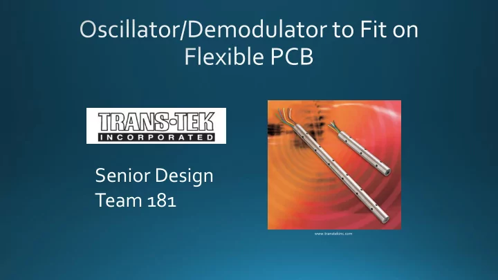

Senior Design Team 181 www.transtekinc.com
Team: • Ryan Williams (EE) • Jonathan Wolff (EE) • Damon Soto (EE) • Jason Meyer (EE) Advisor: Helena Silva (ECE) Trans-Tek Contacts: • Mark Bennett • Jeffrey Gladu
• LVDT Background • Current Oscillator/Demodulator Model • Design Alternatives – Oscillator • Design Alternatives – Demodulator • Final Design • Goals • Progress • Timeline • Budget
• Consists of a 3-part transformer • Secondary coils wired in subtractive configuration • Position of core determines output voltage • Linear relationship between core position and output voltage http://upload.wikimedia.org/wikipedia/commons/0/07/Lvdt_how.gif
http://www.singer-instruments.com/sites/default/files/images/tutorials/how_lvdt_works_fig3.gif
LVDT components: 1. Stainless SteelTubing/housing (top) The LVDT housing will be extended to 2. LVDT pushrod (bottom left) contain the circuitry. 3. Core (bottom right) 4. LVDT Windings (middle)
www.transtekinc.com
www.transtekinc.com
• Second part is the oscillator itself. • Hardware circuit that converts a DC signal to an AC signal. • Frequency of the oscillator is determined by a RC combination, looking for a range of 1.5 to 12.5 kHz. • Output voltage should be 1 VRMS. • Need to make an oscillator with almost no harmonic distortion. http://www.electronics-tutorials.ws/oscillator/osc22.gif
• Third subpart is the amplifier. • Will take the output signal of the Oscillator portion and amplify the wave form. • Output voltage determined by a resistor, looking for 1 to 6 VRMS.
Reference Signal Remove Readout DC Offset Microcontroller DC Offset Device LVDT Output
Receive Determine reference & ADC amplitude ratio output signals Output DC Calculate Identify phase signal (with corresponding shift offset) DC ouput
RIGID • Cheaper • More reliable • Thickness can vary
Notice the small dimensions of the aluminum tubing. The extra space a flexible PCB would give is so small it is negligible. LVDT – Linear Variable Differential Transformer
Recommend
More recommend