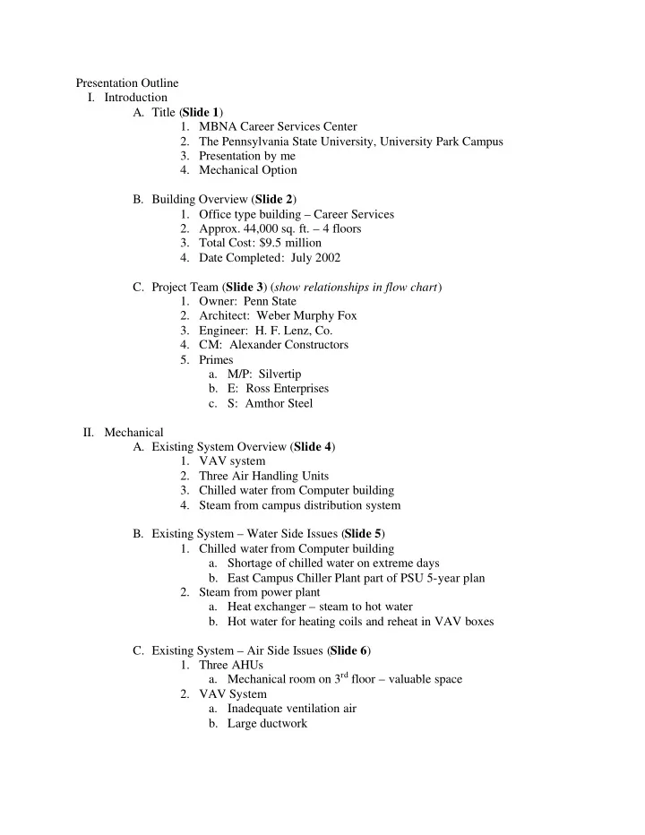

Presentation Outline I. Introduction A. Title ( Slide 1 ) 1. MBNA Career Services Center 2. The Pennsylvania State University, University Park Campus 3. Presentation by me 4. Mechanical Option B. Building Overview ( Slide 2 ) 1. Office type building – Career Services 2. Approx. 44,000 sq. ft. – 4 floors 3. Total Cost: $9.5 million 4. Date Completed: July 2002 C. Project Team ( Slide 3 ) ( show relationships in flow chart ) 1. Owner: Penn State 2. Architect: Weber Murphy Fox 3. Engineer: H. F. Lenz, Co. 4. CM: Alexander Constructors 5. Primes a. M/P: Silvertip b. E: Ross Enterprises c. S: Amthor Steel II. Mechanical A. Existing System Overview ( Slide 4 ) 1. VAV system 2. Three Air Handling Units 3. Chilled water from Computer building 4. Steam from campus distribution system B. Existing System – Water Side Issues ( Slide 5 ) 1. Chilled water from Computer building a. Shortage of chilled water on extreme days b. East Campus Chiller Plant part of PSU 5-year plan 2. Steam from power plant a. Heat exchanger – steam to hot water b. Hot water for heating coils and reheat in VAV boxes C. Existing System – Air Side Issues ( Slide 6 ) 1. Three AHUs a. Mechanical room on 3 rd floor – valuable space 2. VAV System a. Inadequate ventilation air b. Large ductwork
D. Proposed System Overview ( Slide 7 ) 1. DOAS/Energy Recovery Air Handling Unit a. Location - basement 2. Fan Coil Unit (Parallel System) a. Replace each VAV box with a FCU E. Proposed System – DOAS/Energy Recovery AHU ( Slides 8 & 9 ) 1. Maximum required outdoor air – 10,905 cfm 2. SEMCO Pinnacle Unit, Model PVS-18 a. Air Flow Capacity 1) Low: 8,000 cfm 2) Mid: 10,000 cfm 3) High: 14,000 cfm 3. ( show diagram of SEMCO unit in basement with clearances ) 4. Heating/Cooling Coil Sizes 5. Efficiency of heat recovery – ( diagram to show temperatures at various locations within the unit ) F. Proposed System – Fan Coil Units ( Slides 10 & 11 ) 1. Heating Coil – secondary coil in FCU a. Piping already exists throughout the building b. No longer need hot water piping to AHU on 3 rd floor 2. Cooling Coil – main coil in FCU a. Chilled water piping to Fan Coil Units integrated with sprinkler piping(?) b. Primarily sensible cooling to reduce/eliminate condensate 3. ( show diagram of components in FCU ) and/or ( 3D drawing of FCU in ceiling plenum with ductwork to three interview rooms ) 4. FCUs circulate the room air to maintain the temperature required G. Proposed System – Operation Sequence/Controls ( Slides 12 & 13 ) 1. Outdoor air damper on each FCU will have 2 settings a. 20% - unoccupied b. 100% - occupied 2. Interview Rooms/Conference rooms (intermittent occupancy) a. Occupancy of rooms is based on a schedule which is put into a program either daily or weekly b. Only a section of rooms that will be used during that day will receive the amount of OA required c. All other rooms will remain on the unoccupied setting of 20% 1) Saves energy and still prevents contaminants from building up in the space 3. All other spaces a. Daytime – occupied – damper at 100% b. Nighttime – unoccupied – damper at 20%
III. Electrical ( Slide 14 ) IV. Structural ( Slide 15 ) V. Cost Comparison between VAV & DOAS/FCU ( outline costs in a table ) ( Slide 16 ) A. Equipment Cost 1. First Cost 2. Maintenance B. Ductwork Cost (reduction in cost for proposed system) C. Piping Cost (additional piping for chilled water to FCUs) D. Electricity Cost ( use $0.07/kwh for a comparison ) E. Structural Savings (reduction in beam sizes on 3 rd floor?) VI. Conclusions ( Slide 17 ) VII. Thank you ( Slide 18 ) VIII. Questions ( Slide 19 )
Recommend
More recommend