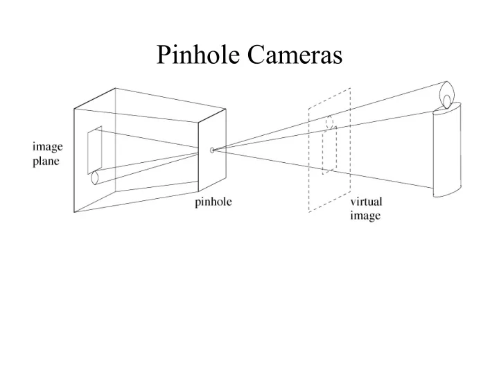

Pinhole Cameras
f 1 y P p z v x ! C u Retinal plane Normalized image plane
Standard Perspective Camera Model Skew of camera axes. ! = 90 o Scale in x direction between world if the axes are perpendicular coordinates and image coordinates Principal point = Image coordinates of the projection of camera origin on the retina Translation between world coordinate system and camera Rotation between world coordinate system and camera Scale in y direction between world coordinates and image coordinates
Alternate Notations By rows: By components: By blocks: Intrinsic parameter matrix 3x3 3x1 3 3x3 3x3 3x1 Extrinsic parameter matrix 4 Q: Is a given 3x4 matrix M the projection matrix of some camera? A: Yes, if and only if det( A ) is not zero Q: Is the decomposition unique? A: There are multiple equivalent solutions
Applying the Projection Matrix Homogeneous coordinates Homogeneous vector transformation: Homogeneous coordinates of point in world p proportional to MP of point in image Computation of individual coordinates:
Geometric Interpretation Projection Observations: equation: • is the equation of a plane of normal direction a 1 • From the projection equation, it is also the plane defined by: u = 0 • Similarly: • ( a 2 , b 2 ) describes the plane defined by: v = 0 • ( a 3 , b 3 ) describes the plane defined by: ! That is the plane passing through the pinhole ( z = 0)
Geometric Interpretation: The rows of the projection matrix describe the three planes defined by the image coordinate system a 3 a 1 v a 2 C u
Other useful geometric properties P p Q: Given an image point p , what is the direction of the corresponding ray in space? A: Q: Can we compute the position of the camera center " ? A:
Affine Cameras Note: If the last row is the coordinates equations degenerate to: The mapping between world and image coordinates becomes linear . This is an affine camera. • Example: Weak-perspective projection model • Projection defined by 8 parameters • Parallel lines are projected to parallel lines • The transformation can be written as a direct linear transformation First 2 components of the translation 2x2 intrinsic between world and camera frames parameter matrix 2x3 matrix = first 2 rows of the rotation matrix 2x4 projection matrix between world and camera frames
Calibration: Recover M from scene points P 1 ,.., P N and the corresponding projections in the image plane p 1 ,.., p N In other words: Find M that minimizes the distance between the actual points in the image, p i , and their predicted projections MP i Problems: • The projection is (in general) non-linear • M is defined up to an arbitrary scale factor
The math for the calibration procedure follows a recipe that is used in many (most?) problems involving camera geometry, so it’s worth remembering: Write relation between image point, projection matrix, and point in space: Write non-linear relations between coordinates: Make them linear:
Write them in matrix form: Put all the relations for all the points into a single matrix: Solve by minimizing: Subject to:
Calibration P i ( u 1 , v 1 ) P 1 MP i ( u i , v i )
Radial Distortion Model
Geometric Distortion
We can follow exactly the same recipe with non-linear distortion: Write non-linear relations between coordinates: Make them linear:
Write them in matrix form: Put all the relations for all the points into a single matrix: Solve by minimizing: Subject to:
From Faugeras
p
Recommend
More recommend