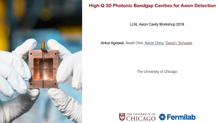

High-Q 3D Photonic Bandgap Cavities for Axion Detection LLNL Axion n Cavit ity Worksho hop p 2018 18 Ankur ur Agrawa wal, Akash Dixit, Aaron Chou, David I. Schuster The University of Chicago
Outline • Introduction to Photonic Band-gap (PBG) cavities • Motivation in the context of dark matter axion detection • Omni-directional PBG cavity • Simulation results 2 Ankur Agrawal | LLNL Cavity Workshop 2018
Photonic Band-gap Material • Band-structure for photons similar to = 13 𝜁 electrons in semiconducting materials = 1 𝜁 • Created by periodic arrangement of contrasting dielectric objects (atoms) • Simplest example is a Bragg reflector in 1-D Δ𝜕 Δ𝜁 • Band-gap size, 𝜕 𝑛 ~ 𝜁 The width of the 𝜁 = 13 layer is 0.2 a , and the width of 𝜁 = 1 layer is 0.8 a Joannopoulos, John D., et al. Photonic crystals: molding the flow of light . Princeton university press, 2011. 3 Ankur Agrawal | LLNL Cavity Workshop 2018
Photonic Band-gap Cavity • Created by introducing a defect site in the lattice Defect • If defect mode frequency lies in the band- gap, then it must exponentially decay once it enters the crystal • Q-values fundamentally limited by the dielectric loss and surface loss at the boundary 𝜇 2 ൗ The red curve is the electric field strength of the defect state associated with this structure 4 Ankur Agrawal | LLNL Cavity Workshop 2018
Axion Dark Matter Haloscope • Cold microwave cavity immersed in a strong static magnetic field (~ 8 Tesla) ⅆ𝑂 𝑏 2 𝑅 𝑑𝑏𝑤 𝑊 ∝ 𝑔 −11 ⅆ𝑢 ∝ 𝐶 0 3 • Superconducting Nb RF cavities with Q~ 10 10 • Copper cavities @ 10 GHz, Q ~ 10 4 SQUID ID Amplifie plifier • High-Q cavities will allow us to Microwave rowave Cavit ity Match the readout cadence to the expected signal photon rate • Cavity Q in excess of the axion Q can be further used for • stimulated emission 8-Tes esla la Magne gnet 5 Ankur Agrawal | LLNL Cavity Workshop 2018
Omni-directional PBG Cavity • FCC-type lattice constructed with Rutile rods (TiO 2 ) in Sapphire • Complete confinement of a defect mode in all directions • Dielectric loss tangent of Rutile and Sapphire is < 10 -6 thus, Q of 10 6 can be achieved • Compact structures can be fit into small magnet bores Johnson, S. G., & Joannopoulos, J. D. (2000). Applied Physics Letters , 77 (22), 3490-3492. 6 Ankur Agrawal | LLNL Cavity Workshop 2018
Simulation Results MIT MPB simulation package 0.25 0.2 Rutile rods arranged in a y (c/2a) trigonal pattern in Sapphire slab 0.15 Δ𝜕 𝜕 𝑛 ~ 31% quency Dielectric constant ( 𝜁 ): Frequen 0.1 Rutile ~ 225 and Sapphire ~ 10 0.05 For band-center @ 10GHz, 0 a ~ 4.11 mm -1.5 -1 -0.5 0 0.5 1 1.5 r ~ 0.293 a ~ 1.26 mm and h ~ 0.93 a ~ 4.0 mm Wave ve vector tor (k/2 𝜌 ) 4-5 periods on each side would be sufficient to exponentially suppress the losses at copper walls Ankur Agrawal | LLNL Cavity Workshop 2018 7
Simulation Results ANSYS HFSS package Air rods in Sapphire substrate Defec fect B A C Defec efect Ankur Agrawal | LLNL Cavity Workshop 2018 8
Summary ▪ PBG Cavities made out of low-loss dielectric material may achieve high Q-values ▪ High contrast dielectric materials allows compact structure to fit in small magnet bores ▪ Cavity Q in excess of axion Q will further help in QND measurement using Qubits Future ure Work: ▪ Test powdered form of dielectric materials to estimate the enhancement in Q ▪ Simulate a woodpile structure (Rutile-Sapphire) to get an idea of Q Ankur Agrawal | LLNL Cavity Workshop 2018 9
Recommend
More recommend