Design and Construction of a Variable Gain Amplifier for Tunable - PowerPoint PPT Presentation
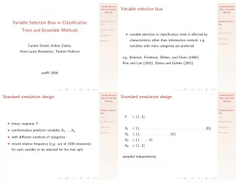
Design and Construction of a Variable Gain Amplifier for Tunable Diode Laser Spectroscopy Robert Moffatt Thomas Jefferson High School for Science and Technology Laboratory:NRL Mentor: Dr. James W. Fleming Introduction My project
Design and Construction of a Variable Gain Amplifier for Tunable Diode Laser Spectroscopy Robert Moffatt Thomas Jefferson High School for Science and Technology Laboratory:NRL Mentor: Dr. James W. Fleming
Introduction • My project supported research done by Dr. James Fleming and Dr. Andy Awtry. • They are investigating how the displacement of oxygen by the evaporation of water mist can be used to put out fires.
Experiment Setup • 760nm laser beam sent through air near flame. Laser • Photodiode Control Amplifier measures light intensity • Signal amplified Laser and sent to computer Photodiode
The Signal Light Output • Laser current from Laser: follows a 2KHz triangle wave. • Wavelength and intensity sweep up Light Input to 760nm and down with Photodiode: current.
Attenuation by Mist • Relative amplitude of Without absorption line Mist: unaffected by mist. • Mist does affect absolute amplitude of signal. • Amplification is With Mist: required to keep the signal above the noise level.
Attenuation by Mist • Attenuation caused by • I designed and mist varies over three constructed circuits to orders of magnitude. solve this problem: an amplifier with • No single gain setting multiple gains, and an on the amplifier amplifier with allowed the entire automatically range to be measured. controlled gain.
Multiple-Gain Amplifier • This multiple-gain amplifier circuit was designed by Dr. Volker Ebert. Laser Control • One input and three Amplifier outputs. • The outputs are monitored Laser simultaneously, so the computer is always Photodiode provided with at least one acceptable signal.
The Schematic • The gain of each output can be switched between two settings: 3 or 6, 10 or 40, and 30 or 250. • The circuit uses three OP27 and OP37 op amps
Auto-Gain Amplifier • Gain controlled automatically • Output measured Laser once per cycle Control Amplifier • Circuit determines if its gain should Laser increase, decrease, or Photodiode remain the same
1MHz MR Sync. 74LS163 Counters Block Diagram: 8 Logic • The circuit consists of Sample In Sample-and-Hold Out three modules: V ref1 V ref2 – A digitally + - + - controlled amplifier Logic – A sampling circuit ENP U/D – Control circuitry 74LS169 Counter Digital 4 Gain Output Demultiplexer & Inverters 8 Digitally Analog Analog Controlled Input Output Amplifier
Results: Multiple-Gain Amplifier Comparison of Fixed Amplfications Water Mist On Decreasing Mist Mist Off 50 No Gain 45 3x Gain 40 10x Gain 35 Oxygen (%) 30x Gain 30 25 20 15 10 5 0 15:50.4 16:07.7 16:25.0 16:42.2 16:59.5 17:16.8 17:34.1 17:51.4 18:08.6 time (min:sec) • A LabView program was used to record and analyze the data. • % O2 is constant; fluctuations are due to noise
Results: Auto-Gain Amplifier Signal Voltage for Variable Gain and Fixed Gain 1.E+01 Increasing Water Mist Density Mist Off Decreasing Mist 2.2V Signal to ADC (volts) 1.E+00 0.7V 1.E-01 Auto Gain Fixed Gain 1.E-02 30:00.0 30:43.2 31:26.4 32:09.6 32:52.8 33:36.0 Time (min:sec) • Input signal varied over 2.5 orders of magnitude. • Signal level maintained within predetermined limits
Results: Auto-Gain Amplifier Oxygen Concentration Measured by Fixed Gain and Auto Gain Increasing Water Mist Density Mist Off Decreasing Mist 50.0 Fixed Gain Oxygen Concentration (%) 40.0 Auto Gain 30.0 20.0 10.0 0.0 30:00.0 30:43.2 31:26.4 32:09.6 32:52.8 33:36.0 Time (min:sec) • Allowed % O2 measurements to be made in high mist densities.
Conclusion • The Multiple-Gain Amplifier was successful. It allowed valid O 2 concentration measurements to be taken during periods of high mist density. • The Auto-Gain Amplifier was successful in controlling the gain and providing valid O 2 concentration measurements.
Acknowledgements • Dr. Fleming (NRL Mentor) • Dr. Awtry (NRC/NRL Postdoctoral Fellow) • Dr. Ebert (Visiting Professor, University of Heidelberg)
Recommend


More recommend
Explore More Topics
Stay informed with curated content and fresh updates.