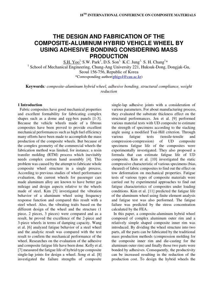
18 TH INTERNATIONAL CONFERENCE ON COMPOSITE MATERIALS THE DESIGN AND FABRICATION OF THE COMPOSITE-ALUMINUM HYBRID VEHICLE WHEEL BY USING ADHESIVE BONDING CONSIDERING MASS PRODUCTION S.H. Yoo 1, S.W. Park 1 , D.S. Son 1, K.C. Jung 1, S. H. Chang 1 * 1 School of Mechanical Engineering, Chung-Ang University 221, Huksuk-Dong, Dongjak-Gu, Seoul 156-756, Republic of Korea *Corresponding author(phigs4@cau.ac.kr) Keywords : composite-aluminum hybrid wheel, adhesive bonding, structural compliance, weight reduction 1 Introduction single-lap adhesive joints with a consideration of Fabric composites have good mechanical properties various parameters. For about manufacturing process, and excellent formability for fabricating complex they evaluated the substrate thickness effect on the shapes such as a dome and egg-box panels [1-3]. structural performances. Jen et al. [9] performed Because the vehicle wheels made of a fibrous various material tests with UD composite to estimate composites have been proved to provide excellent the strength of specimens according to the stacking mechanical performances such as high fuel efficiency angle using a modified Tsai-Hill criterion. Through many efforts have been made to accomplish the mass various fatigue tests (tensile-tensile and production of the composite wheels. But because of compression-compression) of UD composite the complex geometry of the commercial wheels the specimens fatigue life of the composites were fabrication method was limited, for instance, a resin experimentally investigated. They also proposed a transfer molding (RTM) process which inevitably formula that can estimate fatigue life of UD needs complex custom hand assembly [4]. This composite. Kim et al. [10] investigated the static problem was caused by the attempt to fabricate whole compressive characteristic of various specimens (bias, composite wheel structure in a single process. sheared) of fabric composites to find out the effect on According to previous studies of wheel performance tow deformation on mechanical properties. Fatigue evaluation, the current wheels for passenger cars tests of various types of composite materials were made aluminum alloy are known to have better gas carried out by experimental approaches to find out mileage and design aspects relative to the wheels fatigue characteristics of composites under loading made of steel. Kim [5] investigated the vibration conditions. Kim et al. [11] predicted the fatigue life behavior of a aluminum wheel using frequency of the aluminum wheel using finite element analysis response function and compared this result with a and fatigue test was also performed. The fatigue steel wheel. Also, the vibrating traits based on the failure was predicted by the stress concentration different design of the wheel and the structure (1 calculated by the FEA. piece, 2 pieces, 3 pieces) were compared and as a In this paper, a composite-aluminum hybrid wheel result, he proved the excellence of the 2-piece and composed of complex aluminum outer rim and a 3-piece wheels in terms of damping capacity. Wang relatively simple shaped composite inner rim was et al. [6] analyzed fatigue behavior of a steel wheel introduced. By dividing the wheel structure into two and the analytic result was compared with the test parts, all the parts can be fabricated by the traditional result to confirm the mechanical performance of the mass production methods (compression molding for wheel. Researches on the evaluation of the adhesive the composite inner rim and die-casting for the and composite fatigue life have been done. Kelly et al. aluminum outer rim) and finally those two parts were [7] measured the fatigue life of hybrid type composite bonded by adhesives. Consequently, the productivity single-lap joints for design a wheel. Song et al. [8] can be increased resulting in the reduction of the investigated the failure strengths of composite production cost. To design the hybrid wheels the
overall shape and dimension were fixed and only the thickness of 0.5 mm, a special bonding jig was used bonding parts in the inner and the outer rim parts (see Fig. 2). The shape and dimension of the were modified. The bonding length and thickness composite-aluminum single lap joint are shown in were controlled to get the appropriate bonding Fig. 3. The stacking sequence of the composite was strength under several performance tests such as the [0] nT . rotary bending test. Finite element analysis was carried out to determine the bonding thickness and length of the bonding part. For an effective bonding process a groove was machined at the bonding edge of the outer rim part which guaranteed the self-alignment of the two parts during assembling and bonding processes. 2 Experiments 2.1 Tensile test of the adhesive Tensile tests of epoxy adhesives (Loctite 3128) were Fig. 2 Bonding jig carried out in room temperature with the strain rate of 1.3mm/min using a universal testing machine (MTS810, USA). The Tensile tests were carried out following the ASTM D638. The stress-strain relations are shown in Fig. 1. 50 40 Fig.3 The composite-aluminum single lap joint Stress(MPa) 30 specimen. 20 8 10 7 6 0 0.000 0.005 0.010 0.015 0.020 0.025 0.030 5 Stress(MPa) Strain(mm/mm) Fig.1 Stress-strain relationships for a epoxy adhesive 4 (Loctite 3128). 3 2 2.2 Single lap joint test 1 To investigate the bonding strength of a 0 composite-aluminum adhesive joint, single lap joint 0.000 0.002 0.004 0.006 0.008 0.010 0.012 0.014 0.016 0.018 test was carried out with the strain rate of 1.3mm/min Strain(mm/mm) using a universal testing machine (MTS810, USA). Fig.4 Test results from the single lap joint tensile test. The single lap joint test was carried out following the ASTM D1002 and D5868. To sustain the bonding
PAPER TITLE From the single lap joint test it was found that the 3.2 Static bonding strength analysis stress-strain relationship was linear and the bonding From the static lateral compressive analysis it was strength was about 7 MPa as shown in Fig. 4. found that as the bonding thickness and length increased the stress level decreased to 1.50MPa which is much lower stress than the bonding strength 3 FE Analysis measured by a single lap joint test. Table 3 lists the 3.1 Material properties stress in epoxy adhesive according to the bonding thickness and bonding length. The materials used in design of a aluminum-composite hybrid wheel were a aluminum Table 3 Generated maximum shear stress in the T6061-T6, plain weave carbon /epoxy composite epoxy adhesive calculated by FEA. (WSN3k,SK), epoxy adhesive (Loctite 3128) and the Thickness material properties are listed in table 2 below. 0.1mm 0.3mm 0.5mm Table 2 Material properties Young’s Density Length Poisson’s Material 10mm 2.29MPa 1.91 MPa 1.72 MPa ratio Modulus (kg/m 3 ) (GPa) 20mm 1.82 MPa 1.83 MPa 1.73 MPa 2700 68.9 0.3 30mm 2.30 MPa 2.03 MPa 2.13 MPa Yield Ultimate Aluminu Elongation strength strength m (%) 35mm 1.75 MPa 1.61 MPa 1.50 MPa (MPa) (MPa) 276 310 17 Density E x E y 3.3 Rolling rim fatigue analysis (GPa) (GPa) (kg/m 3 ) The safety criterion of the rolling rim fatigue life is Carbon/ 2700 70 70 2,000,000 cycles. To perform the rolling rim fatigue epoxy E z analysis the cosine distributed loading condition at a ν xy ν xz (GPa) part of the rim in radial direction was imposed to simulate the actual driving condition as shown in Fig. 10 0.13 0.13 5. The maximum stresses in epoxy adhesive and X t X c ν yz composite material were calculated according to the (MPa) (MPa) bonding thickness and length and those values were 0.13 778 591 Carbon/ used to estimate fatigue life of the each material. Elongation epoxy From the analysis result it was found that the generated stress levels in all the materials such as (%) epoxy adhesive, composites were low enough for the 1.8 structure to resist over 2,000,000 cycles. (Table 4) Young’s Density Poisson’s Table 4 Result of rolling rim analysis (composite- ratio Modulus (kg/m 3 ) aluminum hybrid wheel) (GPa) Aluminu Adhesive Adhesive Composite 1700 Adhesive 3.9 0.25 m part layer layer part (310MPa) (von mises) (shear) Ultimate Shear Elongation (35MPa) (7.0MPa) strength strength (591MPa) (%) 78.36 1.726 0.2997 17.96 (MPa (MPa) 38 7 2.3 3
bag de-gassing molding process (see Fig. 7). And then the aluminum out rim was bonded using epoxy adhesive with 0.5 bonding thickness after the surface treatment with abrading papers for enhancing bonding strength. Outer rim was designed to have a bump, which is to be matched with a groove formed in the composite inner rim, for self-alignment during bonding process. Fig.5 Rolling rim fatigue analysis From the finite element analyses the bonding length and the thickness were determined to be 35mm and 0.5 mm, respectively. 4 Fabrication of the hybrid wheel A 4-piece aluminum mold was prepared to fabricate a composite inner rim as shown in Fig. 6. Fig. 6 Aluminum mold for fabricating composite inner rim. After the parts of the mold were assembled, the composite prepregs were stacked inside the mold Fig.7 Fabrication of the composite inner rim. surfaces and then cured in an autoclave using vacuum
Recommend
More recommend