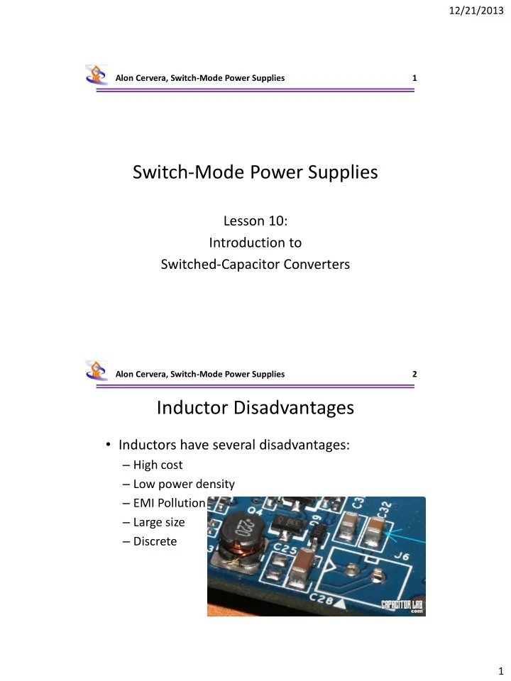

12/21/2013 Alon Cervera, Switch-Mode Power Supplies 1 Switch-Mode Power Supplies Lesson 10: Introduction to Switched-Capacitor Converters Alon Cervera, Switch-Mode Power Supplies 2 Inductor Disadvantages • Inductors have several disadvantages: – High cost – Low power density – EMI Pollution – Large size – Discrete 1
12/21/2013 Alon Cervera, Switch-Mode Power Supplies 3 Steady State Operation Demands • Duality: – Inductor: Volt Sec. = 0 – Capacitor: Ampere Sec = 0 Alon Cervera, Switch-Mode Power Supplies 4 Basic Example (1:1) I C S 1 S 2 C Source Power stage Load • The topology creates voltage balance • Seemingly no straightforward regulation can be done 2
12/21/2013 Alon Cervera, Switch-Mode Power Supplies 5 Charge Profile (‘Complete Charge’) • τ << T s S 1 • What are losses R Δ V C sw dependent on? I C Alon Cervera, Switch-Mode Power Supplies 6 Charge Profile (‘Complete Charge’) • Loss analysis can be done through energy conservation equations 𝐹 𝐷 𝑇𝑋 = 𝐷ΔV 2 2 ∞ ∞ = 𝐷ΔV 2 𝐹 1 = Δ𝑊𝐽 𝑢 𝑒𝑢 = 𝐷Δ𝑊 𝑊 𝐷 𝑢 𝑒𝑢 0 0 𝑚𝑝𝑡𝑡 = 2 𝐷ΔV 2 𝑡 = 𝐷ΔV 2 𝑔 𝑄 𝑔 𝑡 2 3
12/21/2013 Alon Cervera, Switch-Mode Power Supplies 7 Charge Profile (‘Complete Charge’) • An average model can be then composed: 𝑆 𝑓𝑟 = Δ𝑊 2 = 1 𝑡 𝐷 𝑄 𝑔 R eq Load Alon Cervera, Switch-Mode Power Supplies 8 Charge profile (‘No - charge’) • τ >> T s S 1 • Current can be R considered constant Δ V/2 C sw • What are the losses dependent on? I C • Both sub-circuits are literally the same and can be considered as one 4
12/21/2013 Alon Cervera, Switch-Mode Power Supplies 9 Charge profile (‘No - charge’) 2 Δ𝑊 S 1 𝑄 𝑀𝑝𝑡𝑡 = 𝑆 R 2 Δ V/2 C sw 𝑆 𝑓𝑟 = 4𝑆 I C R eq Load Alon Cervera, Switch-Mode Power Supplies 10 Average Model * R i e 10 R eq 8 Load 6 P.C N.C 4 ∗ → 2 C.C 𝑆 𝑓𝑗 * f s ∗ = 𝑆 𝑓𝑗 𝑡∗ = 𝑔 𝑆 𝑓𝑗 𝑔 𝑡 𝑆 𝑗 𝐷 𝑗 2 𝑆 𝑗 0.1 1 10 i i i 𝑆 𝑗 − charge/discharge Ohmic loop resistance t t t 𝐷 𝑗 − charge/discharge loop capacitance 𝑢 𝑗 ≫ R i C i 𝑢 𝑗 ≈ R i C i 𝑢 𝑗 ≪ R i C i 1 ⋅ coth 𝛾 1 1 ⋅ coth 𝛾 2 𝑢 𝑗 1 𝑆 𝑓𝑟 = + , 𝛾 𝑗 = ≈ 𝑗 = 1,2 2𝑔 𝑇 𝐷 1 2 2𝑔 𝑇 𝐷 2 2 𝑆 𝑗 𝐷 𝑗 2𝑔 𝑡 𝑆 𝑗 𝐷 𝑗 𝑆 𝑓1 𝑆 𝑓2 • A good 𝛾 is around 5
12/21/2013 Alon Cervera, Switch-Mode Power Supplies 11 Disadvantages V T V o R S S 1 S 2 Conversion ratio impacts efficiency 𝜃 = 𝑊 𝑃 /𝑊 𝑈 I C V ds P t Hard Switching raises R S Alon Cervera, Switch-Mode Power Supplies 12 Soft Switched SCC • Utilizes the resonant characteristics of an RLC branch • Switch transition occurs at half resonance time 6
12/21/2013 Alon Cervera, Switch-Mode Power Supplies 13 How SSW-SCC works #1 #2 The Capacitor Voltage and Currents for 𝑅 ≫ 1 will behave as following: 𝑗 − Δ𝑊𝑓 −𝛽𝑢 cos 𝜕 0 𝑢 𝐽 𝐷 (𝑢) = 𝜕 0 𝐷 Δ𝑊𝑓 −𝛽𝑢 sin 𝑊 𝐷 𝑢 = 𝑊 (𝜕 0 𝑢) I C V C V 1 #1 #2 #1 #2 V out V in T 0 /2 T 0 t V 2 T 0 /2 T 0 t Alon Cervera, Switch-Mode Power Supplies 14 How SSW-SCC works #1 #2 For 𝑅 ≫ 1 losses are negligible and at first break 𝑊 𝐷,1 ≈ 2𝑊 𝑗𝑜 . • 𝑊 𝑝 = 𝑊 𝑗𝑜 : at second break 𝑊 𝐷 ≈ 0 . V C V 1 #1 #2 • 𝑊 𝑝 < 𝑊 𝑗𝑜 : at second break 𝑊 𝐷 < 0 . – Next cycle: 𝑊 𝐷,1 > 2𝑊 𝑗𝑜 V out – The solution diverges, current V in increases, output voltage increases. • V 2 𝑊 𝑝 > 𝑊 𝑗𝑜 : at second break 𝑊 𝐷 > 0 . – Next cycle: 𝑊 T 0 /2 T 0 𝐷,1 > 2𝑊 t 𝑗𝑜 7
12/21/2013 Alon Cervera, Switch-Mode Power Supplies 15 Soft Switched Capacitor Average * R i Model e 3.5 ∗ = 𝑆 𝑓𝑗 𝑆 𝑓𝑗 𝑆 𝑗 3 R eq Load 2.5 Q i 2 0 1 3 5 10 𝑆 𝑗 − charge/discharge Ohmic loop resistance 𝐷 𝑗 − charge/discharge loop capacitance 2 𝑆 1 ⋅ 𝜚 1 ⋅ tanh 𝜚 1 𝑆 𝑓 = 4𝑅 1 𝑀 𝑗 − charge/discharge loop inductance 𝑆 𝑓1 1 𝝏 𝟏 𝒋 𝑴 𝒋 = 1 𝑀 𝑗 2 𝑆 2 ⋅ 𝜚 2 ⋅ tanh 𝜚 2 𝜕 0 𝑗 = ; 𝑹 𝒋 = + 4𝑅 2 𝑺 𝒋 𝑆 𝑗 𝐷 𝑗 𝑀 𝑗 𝐷 𝑗 𝜌 𝑆 𝑓2 𝜚 𝑗 = ; 𝑗 = 1,2 A good Q factor is around 1 2 − 1 2 ∙ 4𝑅 𝑗 Alon Cervera, Switch-Mode Power Supplies 16 8
12/21/2013 Alon Cervera, Switch-Mode Power Supplies 17 Alon Cervera, Switch-Mode Power Supplies 18 9
12/21/2013 Alon Cervera, Switch-Mode Power Supplies 19 Alon Cervera, Switch-Mode Power Supplies 20 10
Recommend
More recommend