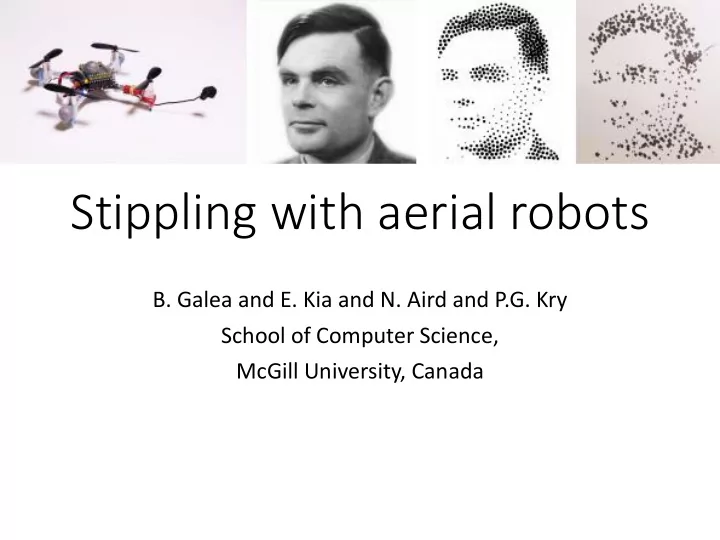

Stippling with aerial robots B. Galea and E. Kia and N. Aird and P.G. Kry School of Computer Science, McGill University, Canada
Introduction
Introduction
Drawing with robotics TRESSET P (2013) Portrait drawing by Paul the robot. LEHNI J (2002), Hektor: Diploma project at ECAL LINDEMEIER T (2015), Hardware-based non-photorealistic LIN C.-Y (2009) Human portrait generation system for robot arm drawing. rendering using a painting robot.
Flying robots in Art SRIKANTH M (2014), Computational rim Sketchy MIT Media Lab illumination with aerial robots.
Stippling MOULD D (2007), Stipple placement using distance in a SECORD A (2002) Weighted Voronoi stippling weighted Graph KIM S (2009), Stippling By Example LI H., MOULD D diffusion (2011), Structure-preserving stippling by priority based error
Aerial robot control MELLINGER D (2012), Trajectory generation and control for precise LANDRY B (2015), Planning and control for quadrotor flight aggressive maneuvers with quadrotors. through cluttered environments.
Our Approach • Filter Position • Compute desired force • Compute robot controls Target pitch, roll, Motion Flight Position (100Hz) Robot yaw and thrust (100Hz) Capture Control Placement Stipple Target Error Onboard PID + Speed Controller Stipple (250Hz) Server
Quadrotor model • Point mass model • align its pitch and roll instantly • Offline system identification • Mass (30.0 grams) • No Inertia Tensor • Motor thrust calibration
Kalman Filtering and State prediction • Smooth's position measurements from motion capture • Provides velocity • Predicts future state to counter system latency
Position Control • PID controller to reach and maintain a desired position • Computes desired net force acting on quadrotor • Send desired roll and pitch commands so the quadrotor is aligned with the force vector
Hover Results • position error of quadrotor from target location over time • Solid and dotted red lines show the mean and standard deviation of the error respectively
Stippling • Consists of 3 stages • Preparation • Stipple action • Recovery 1/16x Speed
Stippling - Preparation • Uses hover controller to approach point normal to target canvas location • Only proceeds to stippling when hover error is below the desired accuracy threshold
Stippling - Preparation • Uses hover controller to approach point normal to target canvas location • Only proceeds to stippling when hover error is below the desired accuracy threshold • Tradeoff between time and accuracy
Stipple Action • Uses an additional PD controller in combination with normal position control • Acts on errors projected into plane of canvas
Stipple Action • Uses an additional PD controller in combination with normal position control • Acts on errors projected into plane of canvas • Detects stipple when distance to canvas below threshold
Stippling - Recovery • Target location near next stipple location • Lasts 50ms • Sets target velocity away from canvas
Stipple video Turing
Radio Communication Improvements • Existing communication not appropriate for real- time communication • Using queue with first-in first-out policy • Required ACKS with high retry count • Disconnect from quadrotor after retry count limit exceeded • Improved protocol • Send most recent command, drop older commands • Lower retry count • ACKs required only occasionally before disconnecting
Software based speed controller • Angular rotor speed generated by the motors is highly dependent on battery voltage • Battery voltage decreases over time and fluctuates based on amount of current being drawn by the motors • Proposed by Landry, runs onboard quadrotor and uses feedback on battery voltage
Stipple Generation and planning • High level planning for where to place stipples and in what order • Dynamically adjusts future stipple placements based on reported errors of previous stipples
Stipple Generation • stipple generation from a source image relies on weighted centroidal Voronoi diagrams (CVD) CVD Algorithm Start with initial random set of points Until stable configuration is reached: compute Voronoi diagram compute region centroids shift points to centroids
Stipple Generate
Stipple Generation
Stipple Generation
Stipple Generation
Stipple Generation
Stipple Generation
Stipple Generation
Stipple Generation
Dynamic Update • Attempts to mitigate errors in stipple placement by adjusting location of future stipples • Re-runs CVD algorithm with location of previous stipples fixed to update future locations
Dynamic Update
Ink Model • Simplified model relies only on number of stipples drawn • Used when planning the order that stipples should be drawn in
Stipple Size • Linearly maps the average brightness for each region to a stipple size • Minimum and maximum radii are computed using the ink model Where 𝑠 𝑛𝑗𝑜 and 𝑠 𝑛𝑏𝑦 are the minimum and maximum radii, and 𝜍 𝑗 is the average pixel brightness across region 𝑗
Path Planning • Three main factors influence the order in which we want to draw stipples 1. Minimize total distance travelled 2. Match stipple size to ink model as best as possible 3. Completed regions should be grown progressively to benefit from dynamic update
Path Planning • Uses a greedy strategy for stippling ordering
Dynamic Update – Synthetic Results Histogram of the inter-stipple distance for the original output without errors (blue), the static stippling with error (red), and the dynamic error adjusted stippling (green), shown for stippling a teapot with 200 points and 1 % standard deviation Gaussian error.
Dynamic Update – Synthetic Results Comparison of synthetic results showing stipples drawn with and without dynamic stipple placement correction for different amounts of error. Error standard deviation of stipple locations in different columns is shown as a per-millimeter of the canvas size.
Physical Prints • Timing and error information for different prints
Physical Prints Grace Kelly (2000 dots)
Conclusion • Low level details involved with aerial flight control • Stipple generation and path planning • Dynamic error correction
Future Work • Typical flight time on battery is less than 6 minutes • Wire tether for continuous flight • Model wire with catenary curve
Future Work – Colored Prints Joker (500 dots)
Future Work • Light painting • Multiple Quadrotor stippling
Thank you for listening
Recommend
More recommend