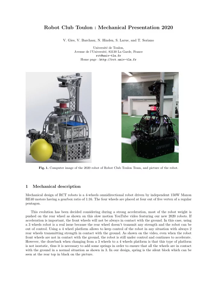

Robot Club Toulon : Mechanical Presentation 2020 V. Gies, V. Barchasz, N. Hinden, S. Larue, and T. Soriano Universit´ e de Toulon, Avenue de l’Universit´ e, 83130 La Garde, France rct@univ-tln.fr Home page : http://rct.univ-tln.fr Fig. 1. Computer image of the 2020 robot of Robot Club Toulon Team, and picture of the robot. 1 Mechanical description Mechanical design of RCT robots is a 4-wheels omnidirectional robot driven by independent 150W Maxon RE40 motors having a gearbox ratio of 1:16. The four wheels are placed at four out of five vertex of a regular pentagon. This evolution has been decided considering during a strong acceleration, most of the robot weight is pushed on the rear wheel as shown on this slow motion YouTube video featuring our new 2020 robots. If acceleration is important, the front wheels will not be always in contact with the ground. In this case, using a 3 wheels robot is a real issue because the rear wheel doesn’t transmit any strength and the robot can be out of control. Using a 4 wheel platform allows to keep control of the robot in any situation with always 2 rear wheels transmitting strength in contact with the ground. As shown on the video, even when the robot front wheels are not in contact with the ground, the robot is still under control and continues to accelerate. However, the drawback when changing from a 3 wheels to a 4 wheels platform is that this type of platform is not isostatic, thus it is necessary to add some springs in order to ensure that all the wheels are in contact with the ground in a normal situation as shown in 3. In our design, spring is the silent block which can be seen at the rear top in black on the picture.
2 V. Gies, V. Barchasz, N. Hinden, S. Larue, and T. Soriano Fig. 2. 4 wheels RCT platform Fig. 3. RCT propulsion element Moves done with this solution are much more reactive than the ones done with our 2019 3 wheels platform using identical motors, especially during strong acceleration phases when the robot tends to pitch up as explained before, or during hard braking phase. 2 Detailled mechanics of the robot
Robot Club Toulon : Mechanical Presentation 2020 3 Fig. 4. Aluminium base : Based on the 2019 experience, most of our robot is now built in 6mm aluminium. Fig. 5. Aluminium base with kicking coil and one of the two capacitor on it.
4 V. Gies, V. Barchasz, N. Hinden, S. Larue, and T. Soriano Fig. 6. Exploded view of the kicking system : iron plunger is in blue, aluminium extension is in red Fig. 7. Base with its 4 motor blocks attached
Robot Club Toulon : Mechanical Presentation 2020 5 Fig. 8. Base with its 4 motor blocks attached in top view
6 V. Gies, V. Barchasz, N. Hinden, S. Larue, and T. Soriano Fig. 9. Motor block with its dampler and belt tightener
Robot Club Toulon : Mechanical Presentation 2020 7 Fig. 10. Exploded view of the motor block Fig. 11. Base with the bottom of the ball handling system : ball caster for slinding the ball are not represented here.
8 V. Gies, V. Barchasz, N. Hinden, S. Larue, and T. Soriano Fig. 12. Base with the ball handling system and the shooting lever Fig. 13. Ball handling system using mecanum wheels
Robot Club Toulon : Mechanical Presentation 2020 9 Fig. 14. Exploded view of the ball handling system using mecanum wheels
10 V. Gies, V. Barchasz, N. Hinden, S. Larue, and T. Soriano Fig. 15. Top part of the robot : this part is mounted on the base with silent blocks in order to reduce vibrations and shocks transmitted to the lidar and camera. These ones are protected against ball shots. Neousys computer is at the bottom of this top part.
Robot Club Toulon : Mechanical Presentation 2020 11 Fig. 16. Final assembly of our robot
Recommend
More recommend