
Lecture 25 Built-In Self-Testing Pattern Generation and Response - PowerPoint PPT Presentation
Lecture 25 Built-In Self-Testing Pattern Generation and Response Pattern Generation and Response Compaction Motivation and economics Definitions Definitions Built-in self-testing (BIST) process BIST pattern generation (PG)
Lecture 25 Built-In Self-Testing Pattern Generation and Response Pattern Generation and Response Compaction � Motivation and economics � Definitions � Definitions � Built-in self-testing (BIST) process � BIST pattern generation (PG) � BIST pattern generation (PG) � BIST response compaction (RC) � BILBO � BILBO Sharif University of Technology Testability: Lecture 25 Page 1 of 50
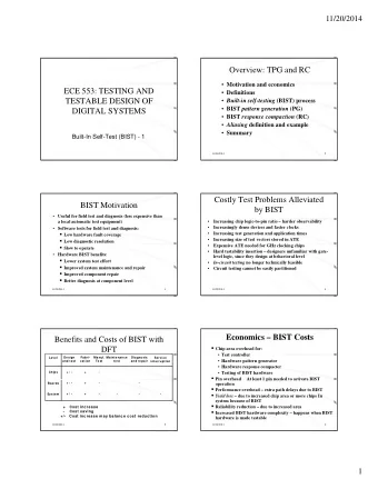
BIST Motivation � Specify test as one of the system functions � self-test � Useful for field test and diagnosis (less expensive than � Useful for field test and diagnosis (less expensive than a local automatic test equipment) � Software tests for field test and diagnosis: g � Low hardware fault coverage � Low diagnostic resolution g � Slow to operate � Hardware BIST benefits: � Lower system test effort � Improved system maintenance and repair � Improved component repair � Better diagnosis Sharif University of Technology Testability: Lecture 25 Page 2 of 50
Costly Test Problems Alleviated by BIST S � Increasing chip logic-to-pin ratio: harder observability � Increasing chip logic-to-pin ratio: harder observability � Increasingly dense devices and faster clocks � Increasing test generation and application times � Increasing test generation and application times � Increasing size of test vectors stored in ATE � Expensive ATE needed for 1 GHz clocking chips p g p � Hard testability insertion– designers unfamiliar with gate-level logic, since they design at behavioral level � In-circuit testing no longer technically feasible � Shortage of test engineers � Circuit testing cannot be easily partitioned Ci i i b il i i d Sharif University of Technology Testability: Lecture 25 Page 3 of 50
Typical Quality Requirements yp Q y q � 98% single stuck-at fault coverage � 100% interconnect fault coverage � Reject ratio – 1 in 100,000 Sharif University of Technology Testability: Lecture 25 Page 4 of 50
Benefits and Costs of BIST with DFT Des Design Fa Fabri- Man Manuf. Maint intenance enance Diagnosis nosis Le Level Ser Servic ice and test and test and r and repa pair ir cation ca tion Test Te test te inter interruption uption + / - + / - + + - - Chip Chips + / - + / - + + - - - Boa Boards + / + / - + + - - - - Syste System - + C C C Cos ost i t i t incr i ncrease ease - Cost sa ost saving ving +/- +/- Cost incr ost increase ease may balance may balance cost r cost reduction eduction Sharif University of Technology Testability: Lecture 25 Page 5 of 50
Economics – BIST Costs � Chip area overhead for: � Test controller � Test controller � Hardware pattern generator � Hardware response compacter � Hardware response compacter � Testing of BIST hardware � Pin overhead: At least 1 pin needed to activate BIST operation Pin overhead: At least 1 pin needed to activate BIST operation � Performance overhead: extra path delays due to BIST � Yield loss : due to increased chip area or more chips in system � Yield loss : due to increased chip area or more chips in system because of BIST � Reliability reduction: due to increased area Reliability reduction: due to increased area � Increased BIST hardware complexity: happens when BIST hardware is made testable Sharif University of Technology Testability: Lecture 25 Page 6 of 50
BIST Benefits � Faults tested: � Single combinational/sequential stuck-at faults � Single combinational/sequential stuck at faults � Delay faults � Single stuck-at faults in BIST hardware � Single stuck-at faults in BIST hardware � BIST benefits � Reduced testing and maintenance cost � Reduced testing and maintenance cost � Lower test generation cost � Reduced storage/maintenance of test patterns � Reduced storage/maintenance of test patterns � Simpler and less expensive ATE � Can test many units in parallel � Can test many units in parallel � Shorter test application times � C � Can test at functional system speed t t t f ti l t p d Sharif University of Technology Testability: Lecture 25 Page 7 of 50
Definitions � BILBO – Built-in logic block observer , extra hardware added to flip-flops so they can be reconfigured as an LFSR pattern generator or response compacter, a scan chain, or as flip-flops � Concurrent testing – Testing process that detects faults during � Concurrent testing – Testing process that detects faults during normal system operation � CUT – Circuit-under-test � Exhaustive testing – Apply all possible 2 n patterns to a circuit with n inputs � Irreducible polynomial – Boolean polynomial that cannot be d bl l l factored � LFSR – Linear feedback shift register, hardware that generates Linear feedback shift register hardware that generates � LFSR pseudo-random pattern sequence Sharif University of Technology Testability: Lecture 25 Page 8 of 50
More Definitions � Primitive polynomial – Boolean polynomial p (x) that can be used to compute increasing powers n of x n modulo p(x) p( ) p g p to obtain all possible non-zero polynomials of degree less than p (x) � Pseudo-exhaustive testing – Break circuit into small, P d h i i B k i i i ll overlapping blocks and test each exhaustively � Pseudo-random testing – Algorithmic pattern generator that � Pseudo random testing Algorithmic pattern generator that produces a subset of all possible tests with most of the properties of randomly-generated patterns � Signature – Any statistical circuit property distinguishing between bad and good circuits � TPG – Hardware test pattern generator r test pattern generator � TPG H rd Sharif University of Technology Testability: Lecture 25 Page 9 of 50
BIST Process � Test controller – Hardware that activates self-test simultaneously on all PCBs � Each board controller activates parallel chip BIST � Each board controller activates parallel chip BIST � Diagnosis effective only if very high fault coverage Sharif University of Technology Testability: Lecture 25 Page 10 of 50
BIST Architecture BIST Architecture � Note: BIST cannot test the following wires and transistors: � From PI pins to Input MUX � From PI pins to Input MUX � From POs to output pins ⇒ High-speed ATE or boundary scan required for these paths ⇒ High-speed ATE or boundary scan required for these paths. Sharif University of Technology Testability: Lecture 25 Page 11 of 50
BILBO – Works as Both a PG and a RC � Built-in Logic Block Observer (BILBO) -- 4 modes: 1. Flip-flop 2. LFSR pattern generator 3. LFSR response compacter 4. Scan chain for flip-flops S h i f fli fl 4 Sharif University of Technology Testability: Lecture 25 Page 12 of 50
Complex BIST Architecture Complex BIST Architecture � Testing epoch I: � LFSR1 generates tests for CUT1 and CUT2 � BILBO2 (LFSR3) compacts CUT1 (CUT2) � Testing epoch II: � BILBO2 generates test patterns for CUT3 � LFSR3 compacts CUT3 response Sharif University of Technology Testability: Lecture 25 Page 13 of 50
Bus-Based BIST Architecture Bus-Based BIST Architecture � Self-test control broadcasts patterns to each CUT over bus – parallel pattern generation � Awaits bus transactions showing CUT’s responses to the patterns: serialized compaction Sharif University of Technology Testability: Lecture 25 Page 14 of 50
Pattern Generation Pattern Generation � Store in ROM – too expensive in chip area � Store in ROM too expensive in chip area � Exhaustive � Pseudo-exhaustive � Pseudo-random (LFSR) – Preferred method � Binary counters – use more hardware than LFSR � Test pattern augmentation � LFSR combined with a few patterns in ROM � Hardware diffracter – generates pattern cluster in neighborhood of pattern stored in ROM Sharif University of Technology Testability: Lecture 25 Page 15 of 50
Exhaustive Pattern Generation Exhaustive Pattern Generation � Sho s that e er state and transition � Shows that every state and transition works orks � For n -input circuits, requires all 2 n vectors � Impractical for n > 20 � I ti l f > 20 Sharif University of Technology Testability: Lecture 25 Page 16 of 50
Pseudo-Exhaustive Method � Partition large circuit into fanin cones into fanin cones � Backtrace from each PO to PIs influencing it � Test fanin cones in parallel (if possible) to reduce time � Reduced # of tests from 2 8 = 256 to 2 5 x 2 = 64 � Reduced # of tests from 2 256 to 2 x 2 64 � Incomplete fault coverage (if test pattern length is shortened from exhaustive in one of two test modes) ) Sharif University of Technology Testability: Lecture 25 Page 17 of 50
Random Pattern Testing Bottom curve: Bottom curve: Random- Pattern Resistant circuit Resistant circuit Sharif University of Technology Testability: Lecture 25 Page 18 of 50
Pseudo-Random Pattern Generation � Standard (Type-I, External) Linear Feedback Shift Register ( (LFSR) S ) � Produces patterns algorithmically – repeatable � Has most of desirable random number properties � H t f d i bl d ti b � Need not cover all 2 n input combinations � Long sequences needed for good fault coverage � Long sequences needed for good fault coverage Sharif University of Technology Testability: Lecture 25 Page 19 of 50
Recommend


More recommend
Explore More Topics
Stay informed with curated content and fresh updates.