FRP FOR SUSTAINABLE PRECAST CONCRETE STRUCTURES Sami Rizkalla - PowerPoint PPT Presentation
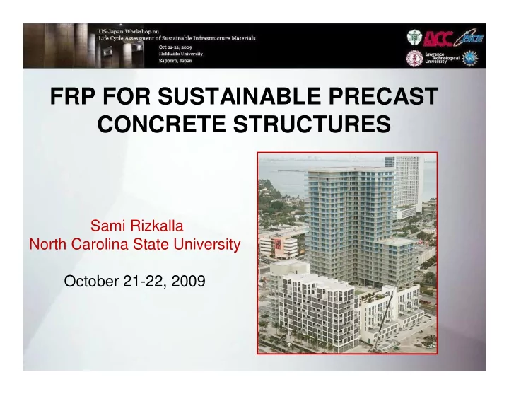
FRP FOR SUSTAINABLE PRECAST CONCRETE STRUCTURES Sami Rizkalla North Carolina State University October 21-22, 2009 1 Underground Precast Utility Tanks 2 1993 Beddington Trail Bridge First Bulb-Tee bridge girder pre- tensioned with CFRP
FRP FOR SUSTAINABLE PRECAST CONCRETE STRUCTURES Sami Rizkalla North Carolina State University October 21-22, 2009 1
Underground Precast Utility Tanks 2
1993 Beddington Trail Bridge First Bulb-Tee bridge girder pre- tensioned with CFRP tendons No signs of degradation when tested in July 2008, 3 after 15 years of service
1997 Taylor Bridge First AASHTO Girder prestressed and Reinforced with CFRP CFRP stirrups Instrumentation of the girder before casting 4 Route 40 Bridge, Virginia
CFFT Piles 700 Confinement 600 effect 500 load (kN) + 400 300 Bending Resistance 200 100 0 0 2 4 6 8 10 12 strain ( µε ) Axial Resistance 5
Power line poles 12 t 5.8 t 6
Recent Innovation for Precast Concrete Products • Double-Tee beams • Wall Panels – Composite – Non-composite • Architectural Cladding 7
“Corrosion Free” Double-Tee Thin flange susceptible to chloride penetration CFRP Grid replacement for WWF conventional steel 8
Carbon Fiber Grids Carbon grids are manufactured in an automated process: – High production volume – High quality control 9
Pre-topped Double Tees 10 10
Pre-topped Double Tees 11
Carbon Fiber Installation - Embedment and finishing machine to place the grid - More precisely for optimum performance - More consistent; less opportunity for human error 12
Research and Development at NC State Uniformly distributed applied load Experimental Program 13
Testing Program 14
Testing Program 15
Testing Program 16
Testing Program Initial Cracking: DT1 DT2 17
Results Failure Mode DT1 2” thick flange 18
Results Failure Mode DT1 2” thick flange 19
Results “Failure” Mode DT2 3.5” thick flange 20
Results 2” thick flange – Midspan 0 2 4 6 8 10 12 -0.1 Measured Vertical Deflection (in.) 0 0.1 Ultimate 0.2 Service 0.3 Factored 0.4 0.5 0.6 0.7 0.8 Distance along DT Profile (ft.) 0 2 4 6 8 10 12 Measured Vertical Deflection (in.) 0 0.2 0.4 Ultimate 0.6 Service 0.8 Factored 1 1.2 1.4 3.5” thick flange – Midspan 1.6 1.8 2 21 Distance along DT Profile (ft.)
Concentrated Load Test Failure load = 11,300 lbs 22
Summary • C-GRID is effective transverse flange reinforcement for precast concrete Double-Tees. • The concentrated load carrying capacity satisfies PCI requirement. 23
Recent Innovation for Precast Concrete Products • Double-Tee beams • Wall Panels – Composite – Non-composite • Architectural Cladding 24
Prestressed Concrete Sandwich Load Bearing Panels - Resist vertical and lateral loads - Provide building envelope - Consists of two concrete wythes and a layer of rigid foam. - Composite action achieved by shear connectors 25
Composite Action & Shear Connection Available FRP shear connectors Discrete Continuous 26
Insulated Sandwich Panel – Orthogonal CFRP Grid – Cut at a 45-degree angle to develop truss action – Structurally and thermally efficient 27
Insulated Sandwich Panel Wythe Reinforcement Exterior Interior Carbon Fiber Pilaster Shear Connector Typical Cross Section Carbon fiber grid shear connectors: - Provide composite action between wythes - Increase insulation value due to low thermal conductivity of the connector 28 28
Experimental Program At NCSU 29
Overall Panel Behavior Lateral Deflection (cm) 0.00 1.27 2.54 3.81 5.08 6.35 25000 111 Composite 20000 89 Representative Lateral Load (lbs) Lateral Load (kN) EPS Panel 15000 67 Ultimate Load 10000 44 Service Load 5000 22 Non-composite 0 0 0.0 0.5 1.0 1.5 2.0 2.5 Lateral Deflection (in) 30
Degree of Shear Connection 31
Experimental Results EPS 2 32 1.2D+0.5L r +1.6W 150
Failure Modes Flexural-shear failure Panel Separation 33
42 foot panel tests 34
Analysis • Theoretical composite and non- Calculation of I eff for composite load-deflection non-composite behavior relationships were calculated following PCI guidelines. ACI 318-08 • Percent composite action was 3 3 M M = + − ≤ cr cr I I 1 I I determined based on deflections eff g cr g M M a a as follows: Valid only for I g /I cr < 3.0 ∆ − ∆ exp x κ = nc (%) 100 Bischoff and Scanlon (2007) ∆ − ∆ c nc I = ≤ cr I I eff g 2 M I − − cr cr 1 1 M I a g 35
Partial Interaction Theory = + + M M M F Z u I O F κ = At the given curvature (%) x 100 F At the full compsoite action 36
Finite Element Analysis CFRP grid 5.5 in. (140 mm) spacing CFRP grid 3.5 in. (89 mm) spacing 8-Node solid elements for foam and concrete 37 Truss elements for C-Grid
Results Strain distribution for EPS2 Panel at service load 8 203.2 Inner wythe 6 152.4 Panel Thickness (mm) Panel Thickness (in) Compression Experimental Tension 4 101.6 Rational model FEA 2 50.8 Outer wythe Outer wythe 0 -500 -300 -100 100 300 500 Strain x 10 6 38
Extreme Events Fire testing 39
GFRP Truss Connector 40
GFRP Truss Connector 41
42
Summary • FRP can provide shear transfer mechanism without thermal breaks in precast prestressed concrete sandwich panels. • Simple rational design approach can be used to determine degree of composite action 43
Recent Innovation for Precast Concrete Products •Double-Tee beams •Wall Panels – Composite – Non-composite •Architectural Cladding 44
Non-Composite Sandwich Panel FRP Connector: Composite Non-composite Panel Panel 45
Thermo graphic image showing: 46 Thermal bridging NO thermal bridging
Recent Innovation for Precast Concrete Products •Double-Tee beams •Wall Panels – Composite – Non-composite •Architectural Cladding 47
Insulated Architectural Panel Vertical Back Ribs Intermediate ribs attached to architectural façade with CFRP grid to avoid discoloration or ‘shadowing’ 48
Insulated Architectural Panel Horizontal Back Ribs Intermediate ribs attached to architectural façade with CFRP grid to avoid discoloration or ‘shadowing’ 49
Panel Configuration Primary vertical rib 6” Typical 50 Carbon fiber grid in the panel face for crack control Secondary vertical rib
Manufacturing Process Placement of CFRP grid reinforcement for 51 architectural facade
Manufacturing Process Foam rib forms FRP shear grid between frame and facade Steel reinforcing of structural frame 52
Full-scale experimental validation Line C B3 7 - C D DC-10 Line B B4 Full-scale testing under reversed cyclic uniform pressure loading representing extreme high-wind loads 53
Inward pressure (suction) Outward pressure 54
Closing Remarks Innovative use of FRP with careful analysis techniques will lead to significant advancements in design, construction and sustainability of precast concrete structures and bridges. Questions? 55
Recommend


More recommend
Explore More Topics
Stay informed with curated content and fresh updates.