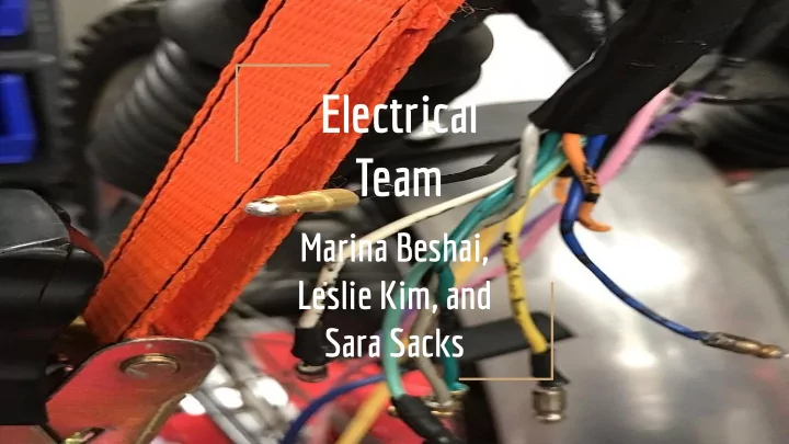

Electrical Team Marina Beshai, Leslie Kim, and Sara Sacks
Overview of the Semester: Learned how to test the point system. ● Learned how to use the oscilloscope. ● Started the portable power generator. ● Solder: ● Learned how to solder, cut wires, remove insulation, and solder two wires together. ○ Wiring harness: ● Graphed the wires, placement, and color. ○ Red motorcycle: ● Cut the clutch cable (2x), and rerouted it. ○ Drilled a hole in the case so that adjusting the springs would be easy. ○ Re-attached the rotor, after replacing 2 missing bolts. ○ Re-attached the gasket and brake. ○
Theory: Science of Soldering 1. Purpose of soldering: a. Soldering forms a connection between two electronic components that allows for an electric current to flow uninterrupted. 2. What is it made of? a. Lead-free solder is an alloy (60% Tin and 40% Zinc) made to melt at a specific temperature. i. Fun Fact! The ratio used to be 60% Lead and 40% Zinc! b. It has often been compared to metal glue. 3. Solder must be capable of holding a joint together. a. What is a joint!? A joint is the technical term for the combination of two wires. b. Kester #44 is the most common solder in the industry. 4. What is a good soldering job? a. A good solder joint should have a shiny finish to it, and not too much solder on it. (Meaning, it shouldn’t be a big blob of solder.) The corners should be slightly curved. The wires should not be e exposed, but the housing should not be melted.
Theory: Our Solder 1. What kind of solder did we use? a. Kester “44” (Industry Standard) 2. What is Kester 44’s Melting Point? a. Around 570° F. 3. What type of flux? a. Fluxes are further divided into two loose groups, acid, which is used for connections where corrosion won't present any particular problems, and rosin, which is a non-corrosive flux used for electrical joints. 4. Fun Fact! a. Our solder was a lead alloy!
Good Solder Job: Notice that the housing is not melted, and the wire is fully covered with solder. Bad Solder Job: Notice that the housing melted, and the wire is exposed.
Application: Clutch Cable Problems 1. The length of the clutch cable itself was too long. 2. The length of the cable outside of the cable jacket was also too long. 3. The current routing of the cable had too many sharp turns. 4. The current routing of the cable was too close to the exhaust, causing the cable to melt. 5. There was not enough tension when pulling the clutch cable. 6. All of this made it extremely difficult to disengage the clutch. 1 2
Application: Clutch Cable Solution 1. We first cut off the cable head of the clutch cable with a wire cutter. 2. We removed the clutch cable. a. This required us to remove the clutch cover on the right side, & unscrew the brake. 3. Conducted research to assess the optimal route so that the clutch cable was as hidden as possible and far away from any hot surfaces, particularly the exhaust pipe to prevent the wire from melting. 4. We measured how much wire to remove using a ruler, and Professor Littman cut off what was deemed to be excess. (x2) 5. We then put the end pieces back on by soldering with the solder pot - Remember the video?
Theory: Engine Rouor and Springs 1. A clutch allows the transmission of rotational energy to be engaged and disengaged. 2. Basically, when the clutch is disengaged, the engine can now spin while the transmission stands still. 3. How does this work? When the clutch is disengaged, the coil springs in the clutch compress, allowing the stacked clutch plates to move independently.
Application: Engine Cover Theory By looking at new Tiger Cub models, we noticed that there was a hole in the clutch cover to allow easy access to the springs. This would allow the rider to easily tighten the clutch screws, to ensure the clutch cable works properly.
Application: Engine Cover Problem 1. Whenever the clutch springs needed to be tightened, one would have to remove the entire engine cover, which is an extremely time and effort intensive task. a. In fact, there are 9 screws. 2. To increase efficiency, we drilled an access hole in the engine cover. a. Therefore, one is able to tighten the springs using a Phillips Screwdriver and Allen Keys without having to remove the case.
Application: Engine Cover Solution 1. We decided to drill a hole on the flat portion of the case (near the tan arrow) to make drilling easier. 2. The exact location of the access point was calculated with respect to an already present spot on the case (Circle A). 3. We calculated the distance from the edge of Circle A to the edge of one of the springs on the motorcycle itself (0.353 in).* 4. We then calculated the radius of the spring (0.2333 in) and the radius of Circle A (0.3135 in). 5. Afterwords, we calculated the distance between the center to center radiuses (.8998 in). 6. 0.8998 in. was thus the distance of the access point with respect to Circle A. Finally, we measured and marked the desired location of the access 7. point, then Glen kindly drilled the hole for us using a drill press. *Only need one access point because if you spin the rotor, Circle A you’ll always be able to adjust for a different spring from the same access point.
Works Cited & Acknowledgements https://www.superstreetbike.com/how-does-motorcycle-clutch-work#page-2 https://www.sciencebuddies.org/science-fair-projects/references/how-to-solder https://eecs.oregonstate.edu/education/docs/tutorials/rogersolder.pdf Electrical would like to thank Kate for her guidance and support.
The End! Questions?
Recommend
More recommend