Dump in the Framework of the LHC Injectors Upgrade Project Summary - PowerPoint PPT Presentation
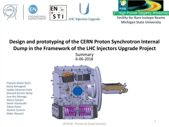
Facility for Rare Isotope Beams Michigan State University Design and prototyping of the CERN Proton Synchrotron Internal Dump in the Framework of the LHC Injectors Upgrade Project Summary 6-06-2018 Franois-Xavier Nuiry Giulia Romagnoli
Facility for Rare Isotope Beams Michigan State University Design and prototyping of the CERN Proton Synchrotron Internal Dump in the Framework of the LHC Injectors Upgrade Project Summary 6-06-2018 François-Xavier Nuiry Giulia Romagnoli Jaakko Johannes Esala Edouard Grenier Boley Jose Briz Monago Marco Calviani Vasilis Vlachoudis Tobias Polzin Yannick Coutron Didier Steyaert 1 HPTW18 - PS Internal Dump Summary
PS Internal Dumps – Outlines - Introduction Operation and PS dump description Requirements - New Dump Core Description Energy deposition studies Thermo-mechanical simulations Prototyping Analysis HPTW18 - PS Internal Dump Summary 2
The PS Machine and LIU PS Upgrade The LHC Injectors Upgrade should plan for delivering reliably to the LHC the beams required for reaching the goals of the HL-LHC. Timeline: Mai 2020 (PS closing) PS Machine: 628 m circumference 100 Main dipoles Max proton momentum: 26 GeV/c SS48 HPTW18 - PS Internal Dump Summary 3
New Dumps: Operation Modes Reference: PS Ring Internal Dump Functional Specifications, EDMS 1582110 v.2.0. Machine Development Cycle in the supercycle not requested for extraction 26GeV DUMP DUMP DUMP Magnetic field 1.2 s 2GeV Time BEAM LHC 25 ns 2015 LHC25ns HL Particles Protons, for LHC 8.7 × 10 12 2.4 × 10 13 Pulse Intensity: Continuous pulses to study Minimum 4 pulses Minimum 4 pulses Beam revolution time: 2.1 µs 2.1 µs Pulse Period (Basic Period): 3.6 s 3.6 s Beam rms size ( σ h x σ v ) odd section [mm × mm] 1.85 x 0.98 1.74 x 0.87 Max momentum 26 GeV/c 26 GeV/c Intensity density* 76 252 Total shaving time approx. 4 ms approx. 4 ms Total beam energy 35 kJ 96.3 kJ Total energy on the dump 3.2 kJ 8.3 kJ T max on dump 415°C 1154°C *Intensity density HPTW18 - PS Internal Dump Summary 4
New PS Dump Description Dimensions 650 mm Mass: 175 kg HPTW18 - PS Internal Dump Summary 5
PS Internal Dumps – Actuation System - Magnetic field keeps the dump arm close to the magnet Magnet current cut springs pushes the dump in the beam position - - Back springs push back the dump in the initial position If problem (magnet current) safety motor pushes away the dump from the chamber - Power supply Power supply MAGNET MAGNET ARM IN ARM IN Vacuum Chamber Vacuum Chamber IN IN SPRING SPRING SPRING SPRING OUT OUT ARM OUT ARM OUT MOTOR MOTOR Return Move Return Move HPTW18 - PS Internal Dump Summary 6
PS Dump Kinematics Beam • Cycle time: <300 ms • Angular movement: +/-6° dump tangential velocity ~0.8 m/s Beam turn after beam turn, the dump intercepts a small fraction of the beam protons PS ring Courtesy: Yannick Coutron (CERN) HPTW18 - PS Internal Dump Summary 7
PS Dump Shaving Impact Nonlinear beam intensity drop over time*: Dump movement ~3-7 ms Gaussian beam Beam intensity intensity distribution PS ring Beam dynamics Time *PS Wall Current Monitor measurement HPTW18 - PS Internal Dump Summary 8
PS Dump Shaving Impact Nonlinear beam intensity drop over time: On a very thin layer of the dump core surface (few tens of Beam intensity microns thick); A 1 degree angle is set in order to control the position of the primary impact location. Time Beam 1 degree Dump Movement HPTW18 - PS Internal Dump Summary 9
Project Main Requirements PS Ring Internal Dump Functional Specifications, EDMS 1582110 v.2.0. Main Requirements Engineering challenges - Minimized dump core mass, considering - Dumping time shall be 300 ms also proton leakage - Beam impact every 1.2 s or 2.4 s for several - Thermal management minutes - Stress evaluation - 200 000 cycles / year / dump - Cooling system inside the vacuum chamber High vacuum (2 x 10 -8 mbar after 24 h of pumping) - - Reliable mechanism - Geometrical constraints (max 955mm space in Z) - Fatigue (mechanism, bellow…) - Short and punctual maintenance (1 per year) - Highly radioactive environment - Lifetime until 2035 - Precise mechanical dimensioning - Efficient modular shielding - Material ageing (Gas production and DPA) HPTW18 - PS Internal Dump Summary 10
Dump Core Design Concept: Isostatic graphite followed by CuCrZr Seamless cooling tubes Two designs studied: Clamped tubes (mechanical contact) Diffusion bonding (Hot Isostatic Pressing) HPTW18 - PS Internal Dump Summary 11
Materials Some low density materials: • Graphite R7550 • Silicon Carbide High elastic modulus (~400 GPa) high stresses. R7550 better known. • Glassy Carbon Low thermal conductivity ~7 W/(m K) HPTW18 - PS Internal Dump Summary 12
Energy Density Distribution (Fluka) HL-LHC beam Values shown are accumulated per pulse BEAM 1800 J/cm 3 /150 µs At the surface only Graphite 40 µm Courtesy: Jose Briz Monago HPTW18 - PS Internal Dump Summary 13
Thermal Simulation 2400×10 10 protons/3.6 s 667×10 10 protons/s Logarithmic! Max. temp. in CuCrZr Initial beam impact point, 8323 joules/3.6 s 2.3 kW Beam LHC 25ns HL-LHC Max. temp. in Graphite 2.4 × 10 13 Intensity Momentum 26 GeV/c Size 1.74 × 0.87 mm×mm Pulse Steady-state + 4. pulse Graphite – CuCrZr 26°C TCC: 1000 W/(m 2 K) Cooling Pipe - Water HTC: 1000 W/(m 2 K) ~180 °C 48 °C Water boiling temperature V= 0.7 m/s 170 °C at 8 bar Steady-state 4 pulses – HL-LHC Graphite: 1378 °C CuCrZr: 207 °C Graphite: 170 °C CuCrZr: 258 °C For boundary condition calculations see: Upgrade of the PS Internal Dump in the Framework of the LHC Injectors Upgrade Project. EDMS No. 1845424 Rev. 0.1 HPTW18 - PS Internal Dump Summary 14
CuCrZr Structural Results, HIP design CuCrZr at peak time Beam LHC 25ns HL-LHC Intensity 2.4 × 10 13 Momentum 26 GeV/c Size 1.74 × 0.87 mm×mm Pulse Steady-state + 4. pulse Global maximum: 84 MPa Yield strength (300 °C) 230 MPa Representative stress 58 MPa Safety Factor 3.96 HPTW18 - PS Internal Dump Summary 15
Graphite Structural Results, HIP design Graphite at peak time Tensile strength 40 MPa Comp. strength 130 MPa Mohr-Coulomb SF 1.17 X 1 mm 150 µm Stress evolution in Graphite in time Z 150 µm 1 mm Mohr-Coulomb Safety Factor: ANSYS Help, Mohr-Coulomb Stress Safety Tool HPTW18 - PS Internal Dump Summary 16 σ 1 is maximum principal stress (tensile) σ 3 is minimum principal stress (compressive)
Expected activation after 1 month of cool down After 10 years of operation: close to 10 mSv/h on the dump, after 1 month of cool down BEAM Courtesy: J. Vollaire, Cern • FLUKA Monte-Carlo code three dimensions dose rate maps • Inermet and Concrete as part of the shielding For 2.4×10 17 protons / year to the dump • 60 kGy / year on mechanism HPTW18 - PS Internal Dump Summary 17
Core Prototyping CuCrZr blocks + 316L tubes HIP process Thermal treatment Final precision machining Alumina coating of all blocks made of CuCrZr to prevent diffusion bonding to the steel tubes and steel casing during HIP HPTW18 - PS Internal Dump Summary 18
Core Prototyping: HIP Process, Thermal Treatment and Ageing AFTER HIP BEFORE HIP • Heating and cooling rate of 5 K/min; • High temperature plateau for 3 h; • High Argon pressure. • Solutionizing (high temperature for 30 min in air); • Water quenching at RT for 10 min (~90 ⁰ /s) ; AFTER thermal treatment, ageing • Ageing at 500 ° C for 6h in air. and machining Steel tubes inner surfaces under vacuum and sealed to limit oxidation during heat treatment HPTW18 - PS Internal Dump Summary 19
Core Prototyping, Analysis Diffusion bonding semi-success Issue analysis • The CuCr1Zr groove was too large (Ø7 mm, tube ~Ø6.3 mm) • At the beginning of the HIP Pressure increase inside the tube (110 MPa) tube swelling • CuCr1Zr housing too large Tube crack After HIP + Heat treatment Before HIP HPTW18 - PS Internal Dump Summary 20
Core Prototyping, Analysis Optical inspections Interface CuCr1Zr-Steel: • Clearly visible • Defects confirmed as voids in the interface (gaps up to 15 µm thick) 2 mm Courtesy: Josep Busom Descarrega HPTW18 - PS Internal Dump Summary 21
Core Prototyping, Analysis SEM observations and Energy Dispersive X-ray analysis Gap, 2 µm thick CuCr1Zr CuCr1Zr 316L tube 316L tube Sub-micron pore At the continuous bonding: Cu Fe, Fe, • 10 µm thick interface Zr inclusions Cr. Cr, • Cr and Zr diffusion at the interface • Sub-micrometric pores in the Ni. CuCr1Zr due to Kinkerdall effect Diffusion bonding accomplished in a part of the interface Courtesy: Josep Busom Descarrega 22 HPTW18 - PS Internal Dump Summary
PS Internal Dumps – Summary • Beam Intercepting Device with challenging requirements; • The multi-turn shaving / damping process is a key parameter for the core design; PS Machine beam circulation simulations output lead to same intensity drop 4 ms energy deposition time (HL-LHC beam) >1000⁰C temperature gradient over few tens of µm of graphite • Water cooling is needed as 2.3 kW can be applied for several minutes • HIP design is challenging but would enhance PS operation from 2020 onwards • Radiation ageing is not expected to be an issue • Actuation system is a key sub-system for the equipment reliability HPTW18 - PS Internal Dump Summary 23
Thanks for your attention HPTW18 - PS Internal Dump Summary 24
Recommend


More recommend
Explore More Topics
Stay informed with curated content and fresh updates.