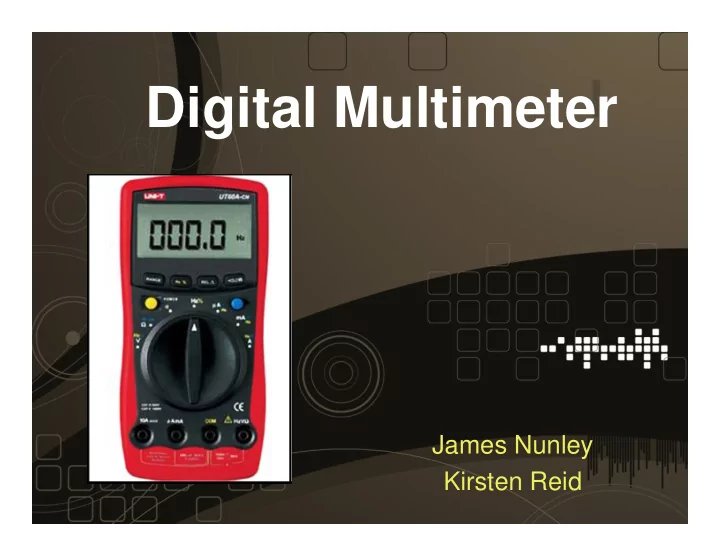

Digital Multimeter James Nunley Kirsten Reid
Project Scope: • Have high / low leads and rotary dial similar to the ones in Lab • Voltage, current, and resistance measurements • Display on an LCD screen • Relatively close values for our resolution • Verified with Fluke Multimeter
Plan of Attack 1. Figure out the measurement circuits for V, I, and R 2. Incorporate multiple channels on the A/D Converter 3. Determination of Resolution
Hardware Components Hardware from Lab: Additional Hardware: – LCD Screen – 6-Position Rotary Switch – A/D Converter – Knob – Potentiometer – Leads – Discrete Circuit Components (Resistors) – Awesome Case
Hardware Block Diagram
Schematic
Pseudocode
Results • Reads: • Accuracy (Best): – Voltage 0 – 5V – Current 0.002 – 0.498 A – +/- 20mV – Resistance – +/- 2 mA • 5 – 5kOhm • 5k – 50kOhm • 50k – 500kOhm – +/- 3 Ohm – +/- 81 Ohm – +/- 1324 Ohm
Obstacles and Opportunities for Improvement Improvements: Obstacles: • Better accuracy with signal • Didn’t start in small steps, conditioning had to start new – Op Amps, diodes, etc. • Figuring out A/D values • Inclusion of AC signals with corresponding to Voltages AC/DC rectifier • Floating inputs to PTM • Continuity function needed to be pulled down • Frequency Measurement of • Limitations in circuit AC signals measuring techniques from lo lead node
Questions
Recommend
More recommend