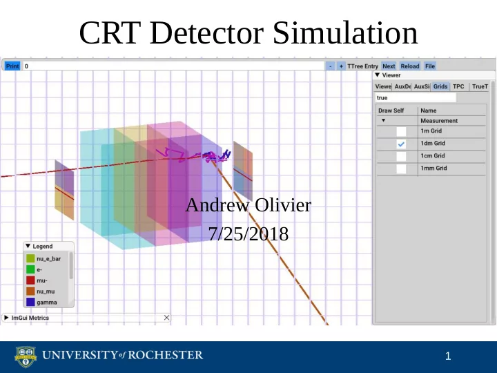

CRT Detector Simulation Andrew Olivier 7/25/2018 1
CRT Simulation Plan artDAQ Particle Generator Detector Simulation Geometry ● Timing CRT Decoder MCTruth ● Energy Deposit Particle Transport ● CRT detected in largeant Trigger ↔ ● Channel mapping AuxDetSimChannel CRT::Trigger Assns MCParticle AuxDetSimChannel Trigger ↔ Track Assns Validation 2
CRT in largeant Started handful of 2GeV muons at -5000mm in z Correct channel mapping → CRT channels line up with MCParticles ProtoDUNE geometry sorts by y, then z, then x Recommend encode detector channel in name X Y Strip Width Distance [mm] 3
System to Simulate Discriminator: FPGA: PMT Anodes, 80 ns OR Fast Shaper PhotoCathode PreAmp Readout Slow Shaper Logic: 32 us The CRT Self-Triggers Reads out ALL channels when one triggers Read out ADCs and one timestamp per trigger 4
Detector Simulation Components Timing Energy → ADC Readout all Scintillator channels? efficiency Data-taking window Photocathode Dead time Amplification “Traffic Jam”? Shapers? 5
Timing Simulation Group hits into 62.5 MHz clock ticks Search windows for hits above threshold Readout if one channel above threshold Keep accepting hits for readout window Write data products CRT::Trigger represents one readout Assns with AuxDetSimChannel for backtracking Skip forward by discriminator dead time 6
Energy Simulation Strategies Birks’ Law in AuxDets? Noticed G4EmSaturation in optical model Prefer to correct as close to Geant as possible Parameterized Detailed Scintillator efficiency: Gaussian Energy → PE from Photocathode: Poisson calibration Amplification: Simulate each PE → ADC from anode? calibration Shapers: TODO 7
Framework Data Format CRT::Trigger CRT::Hit ↔ Trigger Associations Get all information at Don’t have to access once Hits Have to associate Track Can create CRT::Hit ↔ with entire readout recob::Track Assns Fully encapsulates one Have to access Assns → module readout → adds complexity simpler raw::ExternalTrigger CRT::Trigger A Assns A s s s s n n s CRT::Hit CRT::Hit CRT::Hit s CRT::Hit CRT::Hit CRT::Hit 8
Output: What to Expect CRT::Trigger Module number = AuxDet ID Timestamp CRT::Hit Channel number = AuxDetSensitive ID ADC value Assns CRT::Trigger ↔ AuxDetSimChannel Backtracking handle if we need it 9
Future Plans Energy simulation Only use ADC for muon selection? Parameterized for now Quantitative reason for complex model? “Traffic jam” simulation? Understand timing better Cable lengths Read out “empty” Triggers when ADC busy? How often are tokens sent out? 10
Backup: Minimize Framework Coupling Motivation Start testing software during commissioning Later: gallery-powered monitoring? Implementation Data product in separate repository Algorithms in separate repository Coupled to data product Some geometry queries outside of framework? 11
Overview of CRT Hardware From Ed Blucher’s Collaboration Meeting slides Left: 2 layers of 32 channels that are offset by ~25mm Right: 4 frames with 4 modules each on front and back of cryostat 12
CRT in the GDML File dunetpc v06_76_00 Single frame on front and back of cryostat → Need 4 Modules’ dimensions look correct 13
Backup: Visualization of CRT Short red strips are my interpretation of CRT simulation channels Want to map channel to position and look energy and timing 14
Recommend
More recommend