
Why was Discovery Developed? Flow Assurance Needs: There are no reliable subsea detection tools to accurately detect and characterise hydrate, wax, and asphaltene blockages 2
Why was Discovery Developed? Pipeline Integrity Needs: • One third of the world’s oil and gas transmission lines are considered ‘unpiggable’ and cannot be inspected by conventional Inline Inspection (ILI) tools. • No other externally deployed technology is capable of measuring wall thinning through significant coating(s), including internal lines within pipe-in-pipe systems and pipe bundles. 3
The Challenge Develop a subsea inspection device that can: • Accurately measure wall thinning and contents • Inspect through any type and thickness of coatings • Inspect online, irrespective of pipeline contents • Inspect internal pipelines within pipe-in-pipe, pipe bundles, and caissons • Provide results in real time for immediate evaluation • Measure defects to within 1-2mm accuracy 4
• 5
Extensive Trials in 2013 6
Extensive Trials in 2013
Customer Trials in New Test Facilities • Test pieces supplied by customers, for proof of capability prior to offshore projects
Discovery The principle Emanuele Ronchi
Discovery™ Principle Same principle as medical CT scanner • Reconstruct target from a series of projections Important differences • Target is mostly steel, not body tissue (~water) – Using gamma rays instead of X rays • Marinisation is a major challenge – 10000 ft depth rated instrument!
Discovery Initial Prototype Results
Initial Lab Prototype Results SAMPLE 12
Pipe-in-pipe Systems 13
Caissons and Pipe Bundles SAMPLE Oil Riser Gas Riser 14
Discovery The Instrument
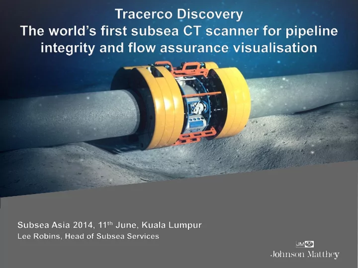
Discovery™ - Animation SOURCE FRAME BUOYANCY DETECTORS 1. Opening
Discovery™ - Animation 2. Positioning
Discovery™ - Animation PADS 3. Clamping HOOK
Discovery™ - Animation 4. Spinning
Discovery™ - Animation SOURCE DETECTORS 4. Spinning (Cutout)
Discovery _ specification overview • Completely non intrusive – No need to remove coating – No need to stop production • Wide range of pipes – 6 to 27 inch. – Integrity and Flow Assurance – Pipe-in-pipe and caissons • 10000 ft / ~3000m Depth • X/Y resolution close to 1mm • Real-time Data Acquisition on the vessel – Images continuously updated every 20-30 seconds
Discovery _ specification overview • Crawler – Instrument automatically advances on the pipe • Scanning speed – ~2-3 ft/h for low resolution – ~0.5 ft/h for high resolution
Discovery Underwater Trials
First Subsea Trial - Bergen, April 2013 24
2nd Subsea Trial – Scotland, 08/13
Customer Trial Results • Test pieces supplied by customers, for proof of capability prior to offshore inspection project
Tracerco Discovery Customer Trial Results – Flow Assurance
Flow Assurance Trial 1 Feature Description Dimensional Information 1 Known feature Object of size 100mm wide x 50mm high, density ~2.4g/cc 2 Known feature Object of size 95mm wide x 210mm high, density ~0.9g/cc 3 Known feature Freeform object of approx. size 100mm x 90mm high, density ~1.9g/cc 4 Known feature Freeform object of approx. size 100mm x 90mm high, density ~1.9g/cc 5 Known feature Fluid filled to approx. 50% of volume, density ~1g/cc 6 Unknown feature Gas pocket of approx. size 70mm wide x 35mm high 28
Flow Assurance Trial 2 • 273mm OD, 15.9mm WT • 10mm internal plastic lining • Manufactured blister to simulate damage
Flow Assurance Trial 3 TEST Detect small gas channel openings in blocked pipelines WHY Assess possibility of gas communication between different sections • MODEL 12 inch Pipe-in-Pipe • Blockage and gas as density-equivalent plastic. Then inserted in the pipe and scanned
Trial 3 – 30 seconds (1 lap) Most channels detected after just 1 lap! MODEL RECONSTRUCTION
Trial 3 – 1 minute (2 laps) Getting Sharper. Now all channels are visible. MODEL RECONSTRUCTION
Trial 3 – 5 minutes (10 laps) Getting Sharper. All channels well visible. MODEL RECONSTRUCTION
Trial 3 – 12.5 minutes (25 laps) All channels completely detected. MODEL RECONSTRUCTION
Flow Assurance Trial 4 HIGH PRESS. GAS ~0.2 g/cc TEST Detecting gas pressure differences in blocked pipelines channels WHY Assess gas communication (HP/LP) between sections of pipeline MODEL • Same Pipe-in-Pipe • Blockage and as density- equivalent plastic to LOW asphaltene or wax. PRESS • HP/LP gas as density- GAS ~0.1 equivalent foam (0.1/0.2 g/cc g/cc)
Trial 4 – 12.5minutes (25 laps) Successful detection of gas density differences in channels. 0.2 g/cc 0.1 g/cc MODEL RECONSTRUCTION
Tracerco Discovery Customer Trial Results – Pipeline Integrity
Integrity Trial 1 TEST Detect wall loss on the inner walls of pipelines • WHY Assess safety margins • Extend service life MODEL • 20 inch pipe, ~20mm wall • Several defect profiles machined at different axial positions in the pipe
Integrity Trial 1 6+1 localized defects and 2 scallops to model wall loss DRAWINGS RECONSTRUCTION
Trial 1 – 30 seconds (1 lap) Early detection of most defects and scallops in 30 seconds . DRAWINGS RECONSTRUCTION
Trial 1 – 5 minutes (10 laps) Image getting sharper. All defects clearly visible. DRAWINGS RECONSTRUCTION
Trial 1 – 20 minutes (40 laps) High resolution image. All defects visible and quantifiable. DRAWINGS RECONSTRUCTION
Integrity Trial 2 ‘Blind test’ with unknown defects in a 20 -inch coated pipeline 3 4 2 1 1 2 3 4
Integrity Trial 3 TEST Detect voids and broken strands in flexible risers • WHY Assess safety margins • Extend service life MODEL • 12-inch flexible riser • 1 strand segment was removed from the outer tensile armor.
Trial 3 – 30 seconds (1 lap) Indication of broken strand at the first lap (30 seconds) . MODEL RECONSTRUCTION
Trial 3 – 12.5 minutes (25 laps) Image getting sharper. More detail on the inner carcass and all other layers. MODEL RECONSTRUCTION
Conclusion • Tracerco and Statoil have cooperated to produce the world’s first Subsea CT Scanning device. • Truly non intrusive technology – Through coating – No need to stop production • Integrity and Flow Assurance • Real time data • Near mm accuracy 47
Recommend
More recommend