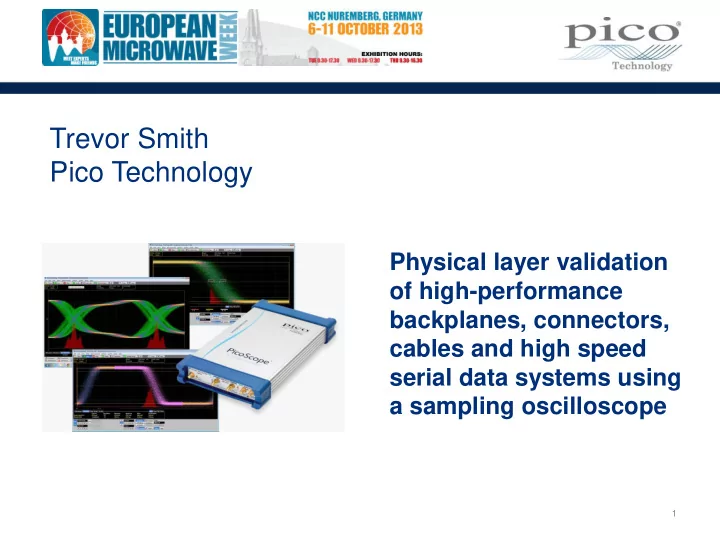

Trevor Smith Pico Technology Physical layer validation of high-performance backplanes, connectors, cables and high speed serial data systems using a sampling oscilloscope 1
Agenda • Introduction • Oscilloscope types, applications and costs • Sampling oscilloscopes • Signal Integrity Measurements • Frequency / Bit Rate / Jitter / Noise / Eye Analysis • TDR / TDT Introduction • Optical • Questions
Introduction Critical Signal Integrity (SI) considerations for high speed digital designs • PCB layout • Backplane design • Connectors • External interfaces • Component performance • Compliance and interoperability with industry standards 3
High Bandwidth Oscilloscopes Real-time Oscilloscopes Sampling Oscilloscopes • Can capture cyclic signals & repeating • Can capture single instantaneous or patterns at steady data rate repetitive events • • Short buffer memory 8-bit ADC resolution, but lower effective bits at high frequencies • Low sample rate • Deep buffer memory • Lower intrinsic jitter and noise • Advanced triggers & display modes to • Eye diagrams and mask testing capture intermittent events • • Serial bus decoding Best choice for TDR/TDT • Ideal for general use and fault diagnosis • Lower, but still significant cost: ~ $50K • for 20 GHz Real-time GS/s sampling is expensive : ~ $200K for 20 GHz 4
PicoScope PC-based instruments PicoScope 9300 • 20 GHz bandwidth • 2 channels • Built-in pattern generator • Automated measurement tools and analysis of clock, data and eye diagrams mask testing • Models with: • Clock recovery to 11.3 Gb/s • Differential TDR/TDT with 40 ps edge • Optical • Low cost: 20 GHz for $15K 5
Real-time Digital Oscilloscope Sample Amplifier ADC Memory And Hold Input signal Trigger Timebase Real-time Digital Oscilloscope 6
Sampling Oscilloscope Sample ADC Memory And Hold Input signal Clock Trigger Sampling Strobe Input Sampling Oscilloscope 7
Analog Bandwidth ‘ Analog bandwidth’ is the maximum frequency that can pass through the front end of an oscilloscope 0 dB -3 dB Amplitude dB 20 GHz Frequency Hz (log) 8
Bandwidth and Rise Time Choose a scope with enough bandwidth for the application: • Signal transition time • Signal clock or data rate • Signal rise and fall time • Signal narrowest pulse Effects of too little bandwidth: • Amplitude and timing errors • Loss of high frequency aberrations and detail 9
Bandwidth and Data Rate Calculating bandwidth from data rate: 3 rd Harmonic = 3 x Bit rate 5 th Harmonic = 5 x Bit rate 2 2 Application example PCIe R1.0a has a data rate of 2.5 Gbps (1.25 GHz frequency) Bandwidth required to see 5 harmonics is 1.25 GHz x 5 = 6.25 GHz V 5 th harmonic 3 rd harmonic 1 st harmonic t 10
Equivalent Time Sampling Sequential Sampling • Data points are acquired sequentially from many cycles to build one screen image • PicoScope 9300 sample rate is 1 MS/s, bandwidth is 20 GHz
Sampling Oscilloscope • Convert high-speed signal (GHz) to a low-frequency copy (kHz) GHz pulses LF copy Sampling Module Sampling Strobe Ext. Trigger
PicoScope 9300 Front Panel 20 GHz 2 channels Clock Data Recovery: 11.3 Gb/s Differential TDR: 40 ps, 200 mV step (6 V, 65 ps step) USB & LAN interfaces PicoSample™ 3 software
Making Basic Measurements Revealed Menu Menu bar and basic controls above RZ Data NRZ Data Pulse 500 MHz Clk 14
Comprehensive Measurements
Comprehensive Measurements …. Auto Measurements 18 X (time) parameters 17 Y parameters 13 Channel to Channel with or without statistics 15 NRZ Time 27 NRZ Y Params with or without statistics 17 RZ Time 26 RZ Y Params with or without statistics 5 FFT Parameters 138 Total Measurements 16
Vertical Histogram 17
Horizontal Histogram 18
Look into My Eyes! Automatic eye measurements and data
9.95 Gb/s with 10 Gb/s Mask
Eye-line Triggering
TDR/TDT • Differential TDR • 65 ps, 6 V step generator built in • 40 ps, 200 mV external generator • Plot voltage, impedance or reflection coefficient against time or distance 22
Optical • 9.5 GHz precision O/E converter • SM & MM connectors • 750 to 1650 nm • Automatic measurements • Extinction ratio • S/N ratio • Eye height & width 23
PicoScope 9300 Applications SIGNAL ANALYSIS • Electrical standards compliance testing • Eye-diagram analysis HIGH-SPEED DIGITAL COMMUNICATIONS • Design and verification of telecom and datacoms elements • Manufacturing and testing for ITU / ANSI conformance RF COMPONENT TESTING • Mask testing • RF components • Cables and connectors • Pulsed RF switches SEMICONDUCTOR TESTING • Microwave & RF characterisation • High-energy physics R & D • Digital design • Informative waveform displays • Microwave & RF characterisation • High-energy physics MANUFACTURING • Digital design • Limit and mask testing • Testing for ITU / ANSI conformance • Automatic test systems • Auto-calibration routine
Summary 9300 Sampling Oscilloscopes • Economical 20 GHz solution • Broad range of SI measurements • Eye diagram analysis • Mask testing for production • Support for popular industry standards • PCIe, SATA, SONET/SDH, Ethernet, RapidIO, InfiniBand . . . plus user-defined • TDR/TDT for validation of cables, connectors, interconnects etc. • Optical • Signal & timing analysis, testing and design of high-speed digital communication systems, network analysis, & semiconductor testing 25
Recommend
More recommend