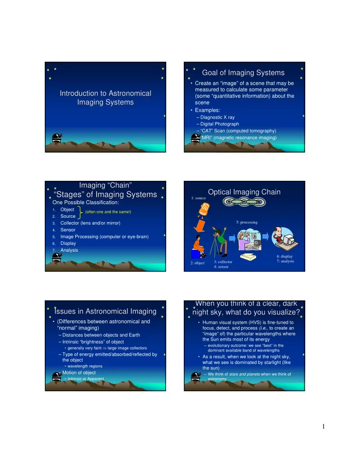

Goal of Imaging Systems Goal of Imaging Systems • Create an “image” of a scene that may be measured to calculate some parameter Introduction to Astronomical Introduction to Astronomical (some “quantitative information) about the Imaging Systems Imaging Systems scene • Examples: – Diagnostic X ray – Digital Photograph – “CAT” Scan (computed tomography) – “MRI” (magnetic resonance imaging) Imaging Imaging “ “Chain Chain” ” Optical Imaging Chain Optical Imaging Chain “Stages “ Stages” ” of Imaging Systems of Imaging Systems 1: source One Possible Classification: Object 1. (often one and the same!) Source 2. 5: processing Collector (lens and/or mirror) 3. Sensor 4. Image Processing (computer or eye-brain) 5. Display 6. Analysis 7. 6: display 7: analysis 3: collector 2: object 4: sensor When you think of a clear, dark When you think of a clear, dark Issues in Astronomical Imaging Issues in Astronomical Imaging night sky, what do you visualize? night sky, what do you visualize? • (Differences between astronomical and • Human visual system (HVS) is fine-tuned to “normal” imaging) focus, detect, and process (i.e., to create an “image” of) the particular wavelengths where – Distances between objects and Earth the Sun emits most of its energy – Intrinsic “brightness” of object – evolutionary outcome: we see “best” in the • generally very faint ⇒ large image collectors dominant available band of wavelengths – Type of energy emitted/absorbed/reflected by • As a result, when we look at the night sky, the object what we see is dominated by starlight (like • wavelength regions the sun) – Motion of object – We think of stars and planets when we think of • Intrinsic or Apparent astronomy 1
Information at Different Information at Different Electromagnetic Spectrum Electromagnetic Spectrum Wavelengths – – Centaurus Centaurus A A Wavelengths X Rays (Chandra) Ultraviolet (GALEX) Visible Light Visible Light Sketch by John Herschel (Anglo-Australian Obs.) Visible Light Radio (VLA) Far IR (IRAS) Near Infrared Mid Infrared (2MASS) (Spitzer Space Telescope) Decreasing Wavelength λ Systems/Sensors for Different λ λ Radio Wavelengths Radio Wavelengths Systems/Sensors for Different • Radio Waves: Radio Telescope • Much longer than visible light • Infrared Light: Telescope w/ IR Camera • Visible Light: Optical Telescope λ ≥ 1 mm • Ultraviolet Light: Space-based Telescope • X Rays: Space-based X-Ray Telescope • Used for TV, Radio, Radar Radio Telescopes Radio Telescopes Radio Telescope Radio Telescope • Diameter of “collector” is very large 100m at Green Bank, WV (10s – 100s of meters) • Large Diameter Necessary to Obtain 305m at Arecibo, Puerto Rico “Angular Resolution” – Ability to distinguish two sources that are close together (separated by a small angle) Image courtesy of NRAO/AUI http://www.naic.edu/about/ao/telefact.htm 2
Imaging Instruments Used for Imaging Instruments Used for Radio vs. Visible, Orion Nebula Radio vs. Visible, Orion Nebula Previous Photos of Orion Nebula Previous Photos of Orion Nebula up to 36 km (22 miles) 25m 4.2m Radio Telescope Array Optical Telescope λ ≈ 207 mm ≈ 207,000,000 nm 700 nm ≥ λ ≥ 400 nm NCSA Astronomy Digital Image Library Image courtesy of NRAO/AUI Very Large Array = VLA Very Large Array = VLA Infrared Wavelengths (IR) Infrared Wavelengths (IR) • Wavelengths λ are longer than for • 27 telescopes • 25m diameter visible light • transportable on rails • separations up to 36 km (22 miles) 25 µ m ≥ λ ≥ 1 µ m • This light is absorbed by water vapor in atmosphere Image courtesy of NRAO/AUI “ “Thermal Infrared Thermal Infrared” ” Astronomy Astronomy Infrared Astronomy Infrared Astronomy • Because “thermal” infrared light is • Conveys information about generated by heat, detector must be temperature cooled to a lower temperature to – i.e., images show “heat” measure the light – Uncooled detector is analogous to camera that also has an internal light source • camera itself generates a measurable signal • Cooling detector is a BIG issue in Courtesy of Inframetrics infrared astronomy 3
X- -Ray Wavelengths Ray Wavelengths Medical X- -Ray Imaging Ray Imaging X Medical X negative image • Much shorter than visible light 0.1n m ≥ λ Medical Imaging: • X-Ray Telescope creates image of 1. X Rays from source are absorbed (or scattered) by dense structures in object (e.g., bones). Much less so by muscles, distribution of X rays in object ligaments, cartilage, etc. 2. Most X Rays pass through object to “expose” X-ray sensor (film or electronic) 3. After development/processing, produces shadowgram of dense structures (X Rays pass “straight through” object without “bending”) X Rays CAN Be Reflected at X Rays CAN Be Reflected at Lenses for X Rays Don’ ’t Exist! t Exist! Lenses for X Rays Don Small Angles ( Grazing Small Angles ( Grazing (It would be very nice if they did!) ( Incidence ) ) Nonexistent Incidence Nonexistent X-Ray X-Ray X-Ray Image Lens “Light Bulb” X-Ray “Mirror” θ X Ray at “Grazing Incidence is “Deviated” by Angle θ (which is SMALL!) X Rays from Object X Rays from Object Summary Summary Strike One of 4 Nested Strike One of 4 Nested • Need Imaging Systems that Can “See” the Entire Spectrum of Wavelengths (“Colors”) Mirrors… Mirrors … – Different Information is Conveyed at Different Wavelengths • X Rays and Gamma Rays • Ultraviolet (UV) Light • Visible Light • Infrared Light Incoming • Radio Waves X Rays • The Different Systems Have VERY Different Requirements 4
Recommend
More recommend