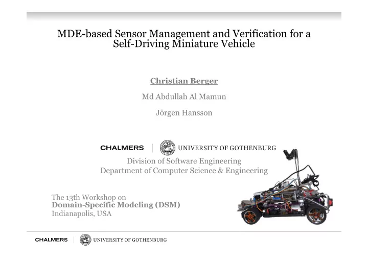

MDE-based Sensor Management and Verification for a Self-Driving Miniature Vehicle Christian Berger Md Abdullah Al Mamun Jörgen Hansson Division of Software Engineering Department of Computer Science & Engineering The 13th Workshop on Domain-Specific Modeling (DSM) Indianapolis, USA
2
3
4
Realizing Sensor Layout Camera LED Board P_138 P_140 P_039 Ultrasonic Ultrasonic Ultrasonic Braking LEDs PandaBoard ES PB6 (SCL) PB9(SDA) Power Supply Flashing STM32F4 Discovery Board LEDs PD8 (TX) left PD9 (RX) PC1 PC4 PC5 PC8 PC9 Flashing Razor LEDs Infrared Infrared Infrared Steer ESC Motor Board right PB7 PB14 PA1 PA7 Power PWM I 2 C Wheel Wheel Wheel Wheel UART ADC USB Encoder Encoder Encoder Encoder Sensor 1 Sensor 2 Sensor 3 Sensor 4 ICU Pxy = Connection PIN 5
MDE-based Sensor Management • DSL to manage sensor layouts and constraints for different use cases: – Use Case A: Evaluating sensor layout – Use Case B: Checking realizability of desired sensor layout
DSL Meta-Model Sensors • • Sensor Properties • Configuration Properties • Execution Platform • Application Platform • Unit Types 7
Use Case A: Evaluating Sensor Layout InstanceModel.xmi% irus.numberOfSensors%=%5% 1 irus.showPolygons%=%1% ...% irus.sensor2.id%=%2% irus.sensor2.name%=%Infrared_RearRight% irus.sensor2.rotZ%=%F90.0% irus.sensor2.transla3on%=%(F1.0;F1.0;0.0)% irus.sensor2.angleFOV%=%5.0% irus.sensor2.distanceFOV%=%3.0% irus.sensor2.clampDistance%=%2.9% irus.sensor2.showFOV%=%1% 2 3 3 Test%3D%track%from%the%simula3on%% 3 Test%2D%track%from%the%simula3on%% 9
Use Case B: Checking Realizability Embedded% DomainF Embedded% System%Data% specific%PIN% System% Sheets% Constraints% Hardware% Manual% Tabular representation of configuration space for multiplexed pins. 10
Use Case B: Checking Realizability Camera LED Board P_138 P_140 P_039 Ultrasonic Ultrasonic Ultrasonic Braking LEDs PandaBoard ES PB6 (SCL) PB9(SDA) Power Supply Flashing STM32F4 Discovery Board LEDs PD8 (TX) left PD9 (RX) PC1 PC4 PC5 PC8 PC9 Flashing Razor LEDs Infrared Infrared Infrared Steer ESC Motor Board right PB7 PB14 PA1 PA7 Power PWM I 2 C Wheel Wheel Wheel Wheel UART ADC USB Encoder Encoder Encoder Encoder Sensor 1 Sensor 2 Sensor 3 Sensor 4 ICU Pxy = Connection PIN 11
Use Case B: Checking Realizability 12
Use Case B: Checking Realizability • Realizability check as graph traversal problem in Prolog: Configuration graph in Prolog: edge(root, final, -). edge(root, pin1, analog). edge(root, pin2, analog). edge(root, pin2, i2c). edge(pin1, pin2, analog). edge(pin1, pin2, i2c). edge(pin1, final, -). edge(pin2, final, -). 13
Use Case B: Checking Realizability “Inference engine” realized as constraint-based graph traversal: 14
Use Case B: Checking Realizability “User interface” to solve the verification query in Prolog: verify(RequiredProperties, Path) :- path(root, final, Path, RequiredProperties). Calling the user interface with a desired configuration: verify([analog, i2c], P) Checking realizability for configurations up to a length of 5: 15
Conclusion & Work in-Progress • Sensor-layout specification and management language as single-point-of-truth: – Configure experiments in the simulation environment – Check realizability on the desired embedded system – Generate code for the HAL of the embedded system • Engineering the HW/SW interface: – Our embedded system: >14.5 million configuration possibilities – Finding a feasible/all possible/the best pin assignment configuration for the interface board – Experimenting with Prolog and Alloy to check realizability Thank you! 16
Thank you! Realizing Sensor Layout Use Case A: Evaluating Sensor Layout InstanceModel.xmi% irus.numberOfSensors%=%5% 1 irus.showPolygons%=%1% ...% irus.sensor2.id%=%2% irus.sensor2.name%=%Infrared_RearRight% irus.sensor2.rotZ%=%F90.0% Camera LED Board irus.sensor2.transla3on%=%(F1.0;F1.0;0.0)% irus.sensor2.angleFOV%=%5.0% P_138 irus.sensor2.distanceFOV%=%3.0% P_039 P_140 Ultrasonic Ultrasonic Ultrasonic Braking irus.sensor2.clampDistance%=%2.9% LEDs PandaBoard ES irus.sensor2.showFOV%=%1% PB6 (SCL) PB9(SDA) Power Supply Flashing 2 STM32F4 Discovery Board LEDs PD8 (TX) left 3 PD9 (RX) PC1 PC4 PC5 PC9 PC8 Flashing Razor LEDs Infrared Infrared Infrared Steer ESC Motor Board right 3 PB7 PA1 PA7 PB14 Test%3D%track%from%the%simula3on%% I 2 C PWM Power 3 Wheel Wheel Wheel Wheel UART ADC USB Encoder Encoder Encoder Encoder Sensor 1 Sensor 2 Sensor 3 Sensor 4 ICU Pxy = Connection PIN Test%2D%track%from%the%simula3on%% 5 11 Use Case B: Checking Realizability Use Case B: Checking Realizability “User interface” to solve the verification query in Prolog: verify(RequiredProperties, Path) :- path(root, final, Path, RequiredProperties). Calling the user interface with a desired configuration: verify([analog, i2c], P) Checking realizability for configurations up to a length of 5: 15 18 17
Recommend
More recommend