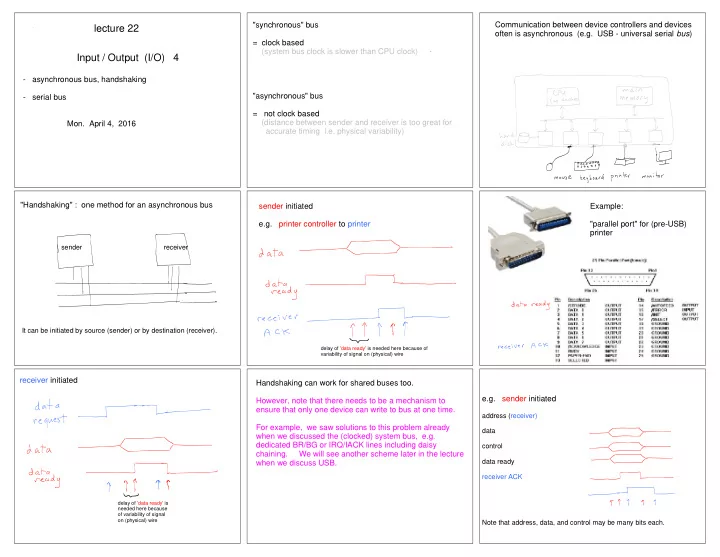

"synchronous" bus Communication between device controllers and devices lecture 22 often is asynchronous (e.g. USB - universal serial bus ) = clock based (system bus clock is slower than CPU clock) Input / Output (I/O) 4 - asynchronous bus, handshaking "asynchronous" bus - serial bus = not clock based (distance between sender and receiver is too great for Mon. April 4, 2016 accurate timing i.e. physical variability) "Handshaking" : one method for an asynchronous bus sender initiated Example: e.g. printer controller to printer "parallel port" for (pre-USB) printer sender receiver It can be initiated by source (sender) or by destination (receiver). delay of 'data ready' is needed here because of variability of signal on (physical) wire receiver initiated Handshaking can work for shared buses too. e.g. sender initiated However, note that there needs to be a mechanism to ensure that only one device can write to bus at one time. address (receiver) For example, we saw solutions to this problem already data when we discussed the (clocked) system bus, e.g. dedicated BR/BG or IRQ/IACK lines including daisy control chaining. We will see another scheme later in the lecture data ready when we discuss USB. receiver ACK delay of 'data ready' is needed here because of variability of signal on (physical) wire Note that address, data, and control may be many bits each.
Parallel bus lecture 22 e.g. receiver initiated - multiple lines Input / Output (I/O) 4 - data needs time to stabilize data request - asynchronous bus, handshaking control Serial - serial bus address (source) - one line Mon. April 4, 2016 data - data doesn't stabilize (next slide) data ready Serial bus e.g. USB How to send bits? (simple model -- one byte) Sender and receiver must agree on a signal pulse duration (greater than their clock pulse duration (typically GHz) i.e. lower signal pulse frequency than clock pulse frequency ). - one line only ! - data doesn't stabiilize, but rather it travels down the wire like a wave start stop - sender and receiver both have clocks (but not signal pulse durations are all the same synchronized and may have very different frequencies) MSB first in this example How to send a file ? Detecting Errors - parity bit Add and extra bit to a byte so that the total number of 1's is even (called 'even parity'). The original ASCII was 7 bits with the 8th bit used for parity. We can detect only if there was an odd number of errors. stop start Note the difference between detection and correction. Parity bits do not allow us to correct the error(s). We would need to send the message again. Receiver samples at a much higher frequency than the pulse frequency Modern methods of 'error correcting codes' use abstract algebra (theory of finite fields) Receiver observers a 1 to 0 transition (start), and waits T/2. If signal is still 0, then it must be a start bit (not noise). Receiver samples every T (duration of pulse) until byte is read (samples in middle of pulses)
USB controller ("host") - polls the USB device UART - universal asynchronous receiver transmitter USB - universal serial bus ("speak when spoken to") - I/O controller and I/O device typically both have one - interrupts the CPU - contain shift registers - can do parity checking too USB USB device controller A: B: plug into plug into computer device (host) A USB bus can have up to 127 devices on it. USB packets Despite the tree structure, the system behaves as a bus . All devices and host see all signals. Fields of a packet include: synch - used to synchronize the clocks of controller and device PID (packet ID) -- what type of packet is it? (r/w ? handshake? ..) address -- which device is it for ? (each device gets a number when it is plugged in) data error correcton info On Windows 7 EXERCISE: Control Panel -> Hardware -> Device Manager -> USB controllers Why can't you just rip out your USB stick from your computer ? Why do you have to formally 'eject' it ? "Plug and play" (plug and pray) - USB host senses a new device, so it interrogates it ("who is the new device who just plugged in?") - USB host then sends info about th device to the OS - OS loads the driver from disk (or tries to get on www) when I plug in my device manufacturers give drivers to Microsoft, Apple printer, this one appears
- image frame is ~20 x 20 pixels Optical Mouse Analog video port - camera capture is 1500 frames/sec I/O controller (graphics card) has an A/D converter - image processing software finds best shift between images Digital video port Announcements A3: - TA email are on page 1 of A3.pdf HDMI - grading scheme is posted on public web page (high definition DVI (digital video interface) multimedia A4: MIPS register conventions abused in my interface - evaluate function. See discussion board. carries audio too) - pick up your quizzes TODO (not on final exam) Wed: thinking about graduate school ? next Mon: Quiz 6 + more on caches next Wed: JVM display port
Recommend
More recommend