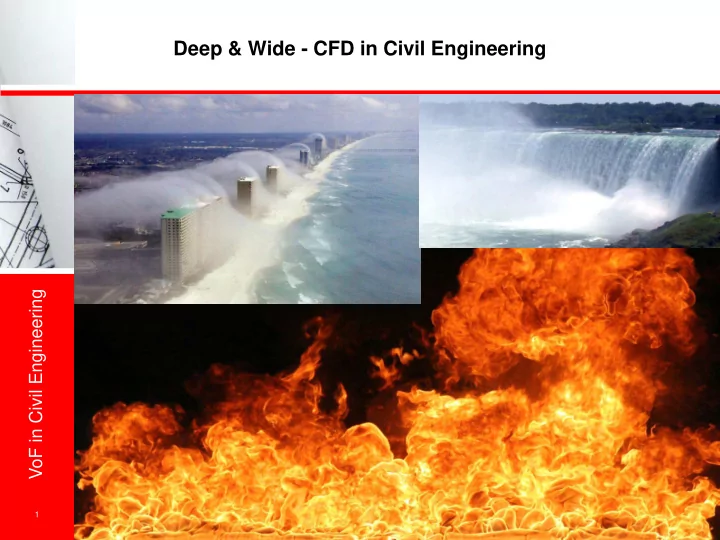

Deep & Wide - CFD in Civil Engineering VoF in Civil Engineering krz/\\ 1
Deep & Wide - CFD in Civil Engineering Fire- and Smoke-Simulation Energy Systems Jet Fans Hydraulic Engineering Aeroelastic Aeroacoustics Emission Prediciton VoF in Civil Engineering CO 2 -Footprint Building Aerodynamics Component Simulation Environmental Aerodynamics Thermal Simulation Process Engineering krz/\\ 2
External Aerodynamics & Windloads VoF in Civil Engineering krz/\\ 3
External Aerodynamics & Windloads VoF in Civil Engineering krz/\\ 4
VoF in Civil Engineering 5 krz/\\ Automotive Test Rig Design
VoF in Civil Engineering 6 krz/\\ Conjugate Heat Transfer
From the Drain to the Tap - VoF in Civil Engineering VoF in Civil Engineering krz/\\ 7
Overview > Water's Way through the Underground > Where VoF can be a useful tool > Three examples in sewerage VoF in Civil Engineering > Limitations > Summary krz/\\ 8
Water's Way Through the Underground > Where does it come from? > How was it treated? > How is it used? VoF in Civil Engineering > Where will it go? > Who will use it next? krz/\\ 9
Water's Way Through the Underground > The well known Hydro Cycle VoF in Civil Engineering krz/\\ 10
Water's Way Through the Underground > The Urban Water "Cycle" VoF in Civil Engineering krz/\\ 11
Where VoF can be a useful Tool > The Urban Water Cycle VoF in Civil Engineering krz/\\ 12
Three Examples of VOF in Drainage Systems > Overflow from Storm Tank > Combined Sewer Overflow (CSO) > High Load Primary Settling Tank VoF in Civil Engineering krz/\\ 13
Overflow from Storm Tank > Scheme of WWTP and StWT WWTP StWT > Scheme of StWT VoF in Civil Engineering odour stopper StWT inlet channel discharge discharge channel towards Rhein krz/\\ 14
VoF in Civil Engineering 15 krz/\\ Overflow from Storm Tank
Overflow from Storm Tank How State of the Art looks like 0.35 4.0 m3/s 0.30 3.9 m3/s 3.5 m3/s 3.0 m3/s 4.5 m3/s (Ausreisser) Höhe über Überfallkante [m] 0.25 1.9 m3/s (Ausreisser) 2.2 m3/s 0.20 3.6 m3/s 3.9 m3/s 3.0 m3/s VoF in Civil Engineering 0.15 2.8 m3/s 0.10 2.6 m3/s 0.05 0.00 0.0 1.0 2.0 3.0 4.0 5.0 6.0 7.0 8.0 9.0 Q MIHABE [m 3 /s] Niveau Becken 1/2 MIHABE idealer Überfall 0.8075 Niveau Becken 3/4 MIHABE hmaxSOLL Instrumente breitkroniges Wehr 0.577 krz/\\ 16
Overflow from Strom Tank How State of the Art looks like 254 253 252 251 Kote [m ü.M.] 250 249 VoF in Civil Engineering 248 247 246 0 10 20 30 40 50 60 70 80 90 Distanz [m] Kanalsohle Q = 6.0 m3/s Kanaldecke Überfallkante EL ARA-Kanal WS ARA-Kanal krz/\\ 17
Overflow from Storm Tank the model VoF in Civil Engineering krz/\\ 18
Overflow from Storm Tank the model VoF in Civil Engineering krz/\\ 19
Overflow from Storm Tank as-is state VoF in Civil Engineering krz/\\ 20
Overflow from Storm Tank as-is state VoF in Civil Engineering krz/\\ 21
Overflow from Storm Tank as-is state VoF in Civil Engineering krz/\\ 22
Overflow from Storm Tank optimisation > slope to prevent the air pumping VoF in Civil Engineering > sluice at odour stopper > higher slope in collector channel krz/\\ 23
Overflow from Storm Tank optimisation VoF in Civil Engineering krz/\\ 24
Overflow from Storm Tank optimisation VoF in Civil Engineering krz/\\ 25
Overflow from Storm Tank optimisation VoF in Civil Engineering krz/\\ 26
Combined Sewer Overflow chamber west CSO storm tank overflow VoF in Civil Engineering storm tank inlet storm tank krz/\\ 27
Combined Sewer Overflow chamber west storm tank overflow CSO VoF in Civil Engineering part of storm tank storm tank inlet krz/\\ 28
High Load Primary Settling Tank VoF in Civil Engineering krz/\\ 29
Limitations > Initial Conditions! > Boundary Conditions! > Computational Limitations! VoF in Civil Engineering > Post Processing Transient Results! krz/\\ 30
Summary > State of the art are 1D St. Venant equations > VOF is an useful tool in urban water management in order to shed light on complex structures VoF in Civil Engineering krz/\\ 31
Recommend
More recommend