
SLIDE 1
1
CS 640: Introduction to Computer Networks
Aditya Akella Lecture 9 - IP: Packets and Routers
2
The Road Ahead
- Last lecture
– How does choice of address impact network architecture and scalability? – What do IP addresses look like? – How to get an IP address?
- This lecture
– What do IP packets look like? – How to handle differences between LANs? – How do routers work?
3
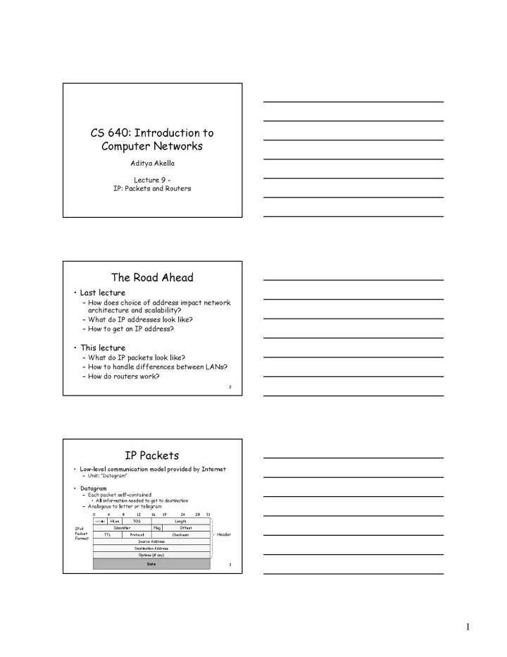
IP Packets
- Low-level communication model provided by Internet
– Unit: “Datagram”
- Datagram
– Each packet self-contained
- All information needed to get to destination
– Analogous to letter or telegram
4 8 12 16 19 24 28 31
version
HLen TOS Length Identifier Flag Offset TTL Protocol Checksum Source Address Destination Address Options (if any) Data Header IPv4 Packet Format