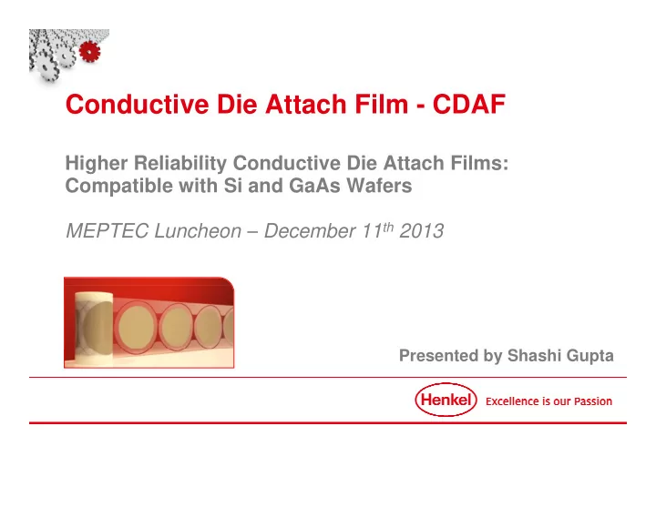
Conductive Die Attach Film - CDAF Hi h Higher Reliability Conductive Die Attach Films: R li bilit C d ti Di Att h Fil Compatible with Si and GaAs Wafers MEPTEC Luncheon – December 11 th 2013 Presented by Shashi Gupta
Contents 1. Market & Package Trend a et & ac age e d 2. Current Material Challenges & Needs 3. cDAF Technology 4. Bulk vs In-package measurements 5. Product Roadmap 6. cDAF on GaAs wafer technology 7. cDAF Advantages 8 8. Summary Summary MEPTEC December 11 th 2013 Luncheon Presentation – Henkel CONFIDENTIAL Slide 2 December 11, 2013
Market Trends Smaller, Faster, Higher Functionalities • Higher density design • Higher functionalities • Faster signal speed • Faster signal speed • Power Management • Lower TCoO • Reduce package thickness Applications space covers consumer, mobile, computing, communication health care, energy, industrial and automotive. MEPTEC December 11 th 2013 Luncheon Presentation – Henkel CONFIDENTIAL Slide 3 December 11, 2013
Market Trends An Example – Source Prismark MEPTEC December 11 th 2013 Luncheon Presentation – Henkel CONFIDENTIAL Slide 4 December 11, 2013
Package Trends - Wirebonded Higher Functionality & Efficiency • Miniaturized packages (QFN, DFN, SOs) • Increased die-to-pad ratio Increased die to pad ratio • In some case D/P ratio close to 1.0 • Thinner packages (QFN, SO, QFP) Thi k (QFN SO QFP) • Packages <0.3mm • Thinner die <75um • Thinner DA bondline thickness <20um • Higher density packages Higher density packages • Multi-dies packages • SiP – LGA/PBGA MEPTEC December 11 th 2013 Luncheon Presentation – Henkel CONFIDENTIAL Slide 5 December 11, 2013
Current Material Challenges on LFs Conducting Die Attach Paste • Dispensing: Optimize dispense patterns for various die sizes - 0.2 x0.2 mm to >10x10mm. • Fill t & Bl Fillet & Bleed: Forces engineers to have a minimum keep out zone around die d F i t h i i k t d di • Bondline Control: Specially for smaller die BLT control is challenging and leads to die tilt • Kerf creep: For thinner wafers uneven fillet height can lead to kerf creep MEPTEC December 11 th 2013 Luncheon Presentation – Henkel CONFIDENTIAL Slide 6 December 11, 2013
Future Material Needs What does the market really need moving forward ? • Lower Cost • Higher Reliability • Higher Reliability • Zero Delamination • Zero Bleed • Minimal fillet • Consistent BLT control • Thin Wafer handling capability • Low to no outgassing • Drop in solution p MEPTEC December 11 th 2013 Luncheon Presentation – Henkel CONFIDENTIAL Slide 7 December 11, 2013
New Materials – Conductive Die Attach Films Controlled flow technology Lamination Process: Lamination Dicing Wafer Wafer Heat Heat Precut cDAF Precut conductive die attach films offer P t d ti di tt h fil ff a single step lamination to wafer back MEPTEC December 11 th 2013 Luncheon Presentation – Henkel CONFIDENTIAL Slide 8 December 11, 2013
Control Flow Enables Miniaturization With Fillet Controlled Fillet MEPTEC December 11 th 2013 Luncheon Presentation – Henkel CONFIDENTIAL Slide 9 December 11, 2013
Control Flow Thin Wafer Handling Package with Fillet Controlled Fillet Height Die Attach Paste Die Attach Film • Thinner wafer handling enabled • Consistent Thinner bondlines achieved • Eliminated Fillet • Eliminated bleed MEPTEC December 11 th 2013 Luncheon Presentation – Henkel CONFIDENTIAL Slide 10 December 11, 2013
Advantages of Control Flow Package level • Enables emerging packages: • Miniaturized • High density • Ultra thin • Indirectly improves package performance: • Faster signal speed (shorter interconnection) • Better power management (low RdSon) • Better heat dissipation p • Indirectly reduces TCoO: • Cheaper design choice (SiP vs. SoC) • Less material used (high packaging density) Less material used (high packaging density) • Improve yield CDAF technology is well-aligned with emerging package trends MEPTEC December 11 th 2013 Luncheon Presentation – Henkel CONFIDENTIAL Slide 11 December 11, 2013
Henkel’s Solution to Control Flow Product Space ormance rmal (Rth) perfo MSL2 on all LF finish DSon) and Ther MSL1 on all LF finish r Electrical (RD MSL2 on Laminates Highe Die Size MEPTEC December 11 th 2013 Luncheon Presentation – Henkel CONFIDENTIAL Slide 12 December 11, 2013
Why CDAF has higher reliability Paste and Film comparison Paste material Film material L Low viscosity i i High viscosity Thermoset monomer with lower Thermoset monomer with higher molecular weight molecular weight (solid resins) High cross-linking density Lower crosslinking density Low toughness High toughness Lower adhesion Lower adhesion Better adhesion Better adhesion Inferior MSL performance Better MSL performance MEPTEC December 11 th 2013 Luncheon Presentation – Henkel CONFIDENTIAL Slide 13 December 11, 2013
Material Benefits of cDAF Potential for Zero Delam applications MC MC Bleed Bleed No Bleed No Bleed CDF 215P Paste Rough Substrate Rough Substrate • Conductive films do not bleed and do not have a fillet so the • Conductive films do not bleed and do not have a fillet, so the adhesion of MC to LF is stronger – regardless of LF finish: smooth or rough. • CDAF also has minimal out-gassing, which ensures clean WB bond pads & die top – • wirebonding or MC-die top delamination not observed MEPTEC December 11 th 2013 Luncheon Presentation – Henkel CONFIDENTIAL Slide 14 December 11, 2013
Thermal & Electrical for cDAF Stable In-Package performance • Thermal Conductivity [W/mK] is an intrinsic material property • Thermal Resistance, R th [K/W], is a geometry dependant value that allows us to better compare materials in a functional package • 70 70 – 90% of the R th is due to the interfaces and is not captured in thermal 90% f th R i d t th i t f d i t t d i th l conductivity values Conductive films are designed to have optimal performance in the z-axis direction Conductive films are designed to have optimal performance in the z axis direction MEPTEC December 11 th 2013 Luncheon Presentation – Henkel CONFIDENTIAL Slide 15 December 11, 2013
Portfolio of CDAF Products Property table for film and paste unit CDF 200P QMI519 84-1LMI SR4 8290 8008HT CDF 800P QMI529HT CDF 500P FS849-TI CDF 600 2100A Material Property Volume Resistivity ohm-cm 0.0014 0.0001 0.0002 0.008 0.00006 0.0003 0.00004 0.0002 0.00002 0.0008 0.05 Thermal conductivity W/mK 2 3.8 2.5 1.6 11 3.5 6.5 1 - 2 7.8 1 1.35 CTE alpha1 ppm/C 48 40 40 81 37 40 53 60 44 75 65 CTE alpha 2 CTE l h 2 ppm/C /C 120 120 140 140 150 150 181 181 62 62 118 118 156 156 245 245 155 155 320 320 200 200 Tg °C 15 75 120 38 264 11 3 10 211 "-5 60 Modulus @ 25C Mpa 5,400 5,300 3,930 3,034 6,659 7,100 3,300 11,300 7,800 3,000 3,200 Modulus @ 250C Mpa 1,000 287 303 117 2,450 900 - 130 1,070 40 230 Performance HDSS (260°C) on Ag kg/mm^2 1.3 0.8 0.2 0.6 0.7 1.0 0.5 0.7 0.5 0.7 0.4 Room Temp DSS on PPF kg/mm^2 2.14 4.9 3.0 5.0 - > 2.0 - - - - - Room Temp DSS on Ag kg/mm^2 3.02 4.8 2.3 5.1 1.5 > 2.0 2.2 - - - - Room Temp DSS on Cu R T DSS C k / kg/mm^2 ^2 3 17 3.17 1 8 1.8 1.2 1 2 2 5 2.5 1 5 1.5 > 2 0 > 2.0 - - - - - Cohesive Cohesive Cohesive Cohesive - Cohesive Cohesive Cohesive - Cohesive Cohesive Failure Mode Thermal Resistance, Rth K/W 1.5 1.3 0.83 1.8 1.5 0.81 0.77 1.5 0.72 2.1 2.3 RDSon ohm 0.075 0.044 0.033 n/a 0.067 0.032 0.042 0.055 0.038 n/a n/a % 2.2 n/a 10.0 n/a n/a 5.7 42 n/a 28.0 n/a n/a RDSon Shift (500 TC) RDSon Shift (1000 TC) % 6.6 n/a 15.6 n/a n/a 6.4 42 n/a 28.8 n/a n/a JEDEC MSL 260°C MSL1 MSL1 MSL1 MSL1 MSL level 1 capable for 3 capable for 3 1 capable for 1 capable for 2 (PBGA) 2 (PBGA) (on 7x7mm PPF QFN with small die ll di small die ll di small die ll di small die ll di 2.5x2.5x0.33 die) JEDEC MSL 260°C MSL level 2 - - - - 2 - 1 3 2 (PBGA) 2 (PBGA) (on 7x7mm PPF QFN with 5x5x0.36 die) Processing 30 min. ramp 30 min ramp + hold 60 30 min ramp 30 min ramp 30 min ramp 30 min ramp 30 min ramp 30 min ramp + 30 min ramp min @ 100°C 30 min ramp to to 200C to 200C + to 175C to 175C + 20 seconds 20 seconds to 200C + to 200C to 185C + 30 to 185C 30 to 200C to 200C + to 175C + 30 to 175C 30 100C/30min 100C/30min to 175C + to 175C Cure C profile f + 15 min 175C + 1hr C 1hr soak @ 15min soak @ 280°C 1hr soak @ min soak @ 1hr soak @ min soak @ + 30 min 15min soak ramp + hold soak @ 175C 200C @ 175C 200C 185C 200C 175C ramp + @ 175C 60 min @ 170C/1hr 200°C. MEPTEC December 11 th 2013 Luncheon Presentation – Henkel CONFIDENTIAL Slide 16 December 11, 2013
Thermal Resistance 2.5x2.5x0.36mm² Si-back die Comparison of paste and film materials QFN 7x7mm, PPF (pad 5.8x5.8mm) QFN 7x7mm, PPF (pad 5.8x5.8mm) 30min RAMP + 200°C 1hr cure MEPTEC December 11 th 2013 Luncheon Presentation – Henkel CONFIDENTIAL Slide 17 December 11, 2013
Recommend
More recommend
Unleash a World of Digital Possibilities—Browse, Share, and Explore Content Without Boundaries