
Computer Graphics CS 543 Lecture 8 (Part 1) CS 543 Lecture 8 (Part - PowerPoint PPT Presentation
Computer Graphics CS 543 Lecture 8 (Part 1) CS 543 Lecture 8 (Part 1) Hierarchical 3D Models Prof Emmanuel Agu Computer Science Dept. Worcester Polytechnic Institute (WPI) Obj Objectives ti Examine the limitations of linear modeling
Computer Graphics CS 543 – Lecture 8 (Part 1) CS 543 Lecture 8 (Part 1) Hierarchical 3D Models Prof Emmanuel Agu Computer Science Dept. Worcester Polytechnic Institute (WPI)
Obj Objectives ti Examine the limitations of linear modeling Examine the limitations of linear modeling Symbols and instances Introduce hierarchical models I t d hi hi l d l Articulated models Robots R b Introduce Tree and DAG models
I Instance Transformation t T f ti Start with unique object (a symbol ) Start with unique object (a symbol ) Each appearance of object in model is an instance Must scale, orient, position l Defines instance transformation
S Symbol ‐ Instance Table b l I t T bl Can store a model by assigning number to each Can store a model by assigning number to each symbol and storing parameters for instance transformation
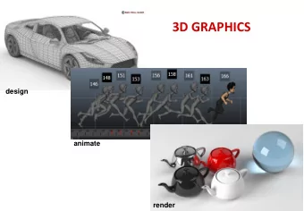
R l ti Relationships in Car Model hi i C M d l Symbol instance table does not show Symbol ‐ instance table does not show relationships between parts of model Consider model of car Consider model of car Chassis + 4 identical wheels Two symbols y Rate of forward motion determined by rotational speed of wheels
Structure Through Function Calls St t Th h F ti C ll car(speed) car(speed) { chassis() wheel(right_front); ( ) wheel(left_front); wheel(right rear); g _ wheel(left_rear); } Fails to show relationships well Look at problem using a graph p g g p 6
G Graphs h Set of nodes and edges (links) Set of nodes and edges (links) Edge connects a pair of nodes Directed or undirected d d d Cycle : directed path that is a loop loop loop 7
Tree Graph in which each node (except the root) has Graph in which each node (except the root) has exactly one parent node May have multiple children May have multiple children Leaf or terminal node: no children root node root node leaf node 8
T Tree Model of Car M d l f C 9
R b t A Robot Arm parts in their own parts in their own robot arm coodinate systems 10
A ti Articulated Models l t d M d l Robot arm is example of articulated model Robot arm is example of articulated model Parts connected at joints Can specify state of model by C if f d l b giving all joint angles 11
R Required Matrices i d M t i Rotation of base: R b Rotation of base: R b Apply M = R b to base Translate lower arm relative to base: T lu Translate lower arm relative to base: T lu Rotate lower arm around joint: R lu Apply M = R b T lu R lu to lower arm Apply M R b T lu R lu to lower arm Translate upper arm relative to upper arm: T uu Rotate upper arm around joint: R uu Rotate upper arm around joint: uu Apply M = R b T lu R lu T uu R uu to upper arm 12
Hi Hierarchical Transforms hi l T f Robot arm: Many small parts Robot arm: Many small parts Attributes (position, orientation, etc) depend on each other each other hammer A Robot Hammer! lower arm base
Hi Hierarchical Transforms hi l T f Object dependency description using tree Object dependency description using tree structure Root node Root node Base Base Object position and orientation can be affected by its parent, grand-parent, grand-grand-parent Lower arm … nodes d Upper arm Hierarchical representation is known as Scene Graph Leaf node Hammer
T Transformations f ti Two ways to specify transformations: Two ways to specify transformations: (1) Absolute transformation: each part of the object is transformed independently relative to the origin transformed independently relative to the origin Translate the base by (5,0,0); Translate the lower arm by (5,0,0); Translate the upper arm by (5,0,0); y … x z
R l ti Relative Transformation T f ti A better (and easier) way: A better (and easier) way: (2) Relative transformation: Specify the transformation for each object relative to its t f ti f h bj t l ti t it parent Step 1: Translate base and p its descendants by (5,0,0);
R l ti Relative Transformation T f ti Step 2: Rotate the lower arm and all its descendants relative to the base’s local y axis by -90 degree y y g y y z x x z
R l ti Relative Transformation T f ti Represent relative transformation using scene Represent relative transformation using scene graph Base Base T Translate (5,0,0) l t (5 0 0) Lower arm Rotate (-90) about its local y Upper arm Apply all the way pp y y down Apply all the way Hammer down
Hi Hierarchical Transforms Using OpenGL hi l T f U i O GL Translate base and all its descendants by (5 0 0) Translate base and all its descendants by (5,0,0) Rotate lower arm and its descendants by ‐ 90 degree about local y ctm = LoadIdentity(); y(); Base … // setup your camera ctm * = Translatef(5 0 0); ctm * = Translatef(5,0,0); Lower arm Draw_base(); U Upper arm ctm * = Rotatef(-90, 0, 1, 0); Draw_lower _arm(); Hammer Hammer Draw upper arm(); Draw_upper_arm(); Draw_hammer();
O OpenGL Code for Robot GL C d f R b t mat4 ctm; mat4 ctm; robot_arm() { ctm = RotateY(theta); ( ) base(); ctm *= Translate(0.0, h1, 0.0); ctm *= RotateZ(phi); lower_arm(); ctm *= Translate(0 0 ctm = Translate(0.0, h2, 0.0); h2 0 0); ctm *= RotateZ(psi); upper_arm(); } } 20
H Humanoid Figure id Fi 21
B ildi Building the Model th M d l Can build model using simple shapes Can build model using simple shapes Access parts through functions torso() () left_upper_arm() Matrices describe position of node with respect d b f d h to its parent M lla positions left lower leg with respect to left upper l f l l h l f arm 22
T Tree with Matrices ith M t i 23
T Transformation Matrices f ti M t i There are 10 relevant matrices There are 10 relevant matrices M positions and orients entire figure through the torso which is the root node torso which is the root node M h positions head with respect to torso M lua , M rua , M lul , M rul position arms and legs with l position arms and legs with M l M M l l M respect to torso M lla , M rla , M lll , M rll position lower parts of limbs with lla rla lll rll respect to corresponding upper limbs 24
glPushMatrix and glPopMatrix lP hM t i d lP M t i Two important calls: PushMatrix( ): Save current modelview matrix in stack PopMatrix( ): restore transform matrix to what it was before PushMatrix( ) ( )
PopMatrix and PushMatrix Illustration i S in Stack k Ref: Computer Graphics Through OpenGL by Guha
St Stack ‐ based Traversal k b d T l Set model ‐ view matrix to M and draw torso Set model view matrix to M and draw torso Set model ‐ view matrix to MM h and draw head For left ‐ upper arm need MM lua and so on For left upper arm need MM and so on Rather than recomputing MM lua from scratch or using an inverse matrix, we can use the i i t i th matrix stack to store M and other matrices as we traverse the tree we traverse the tree 27
T Traversal Code l C d save present model view matrix save present model-view matrix figure() { figure() { PushMatrix() update model-view matrix for head torso(); Rotate (…); recover original model-view matrix head(); PopMatrix(); PopMatrix(); save it again sa e it again PushMatrix(); update model-view matrix Translate(…); for left upper arm for left upper arm Rotate(…); ( ) left_upper_arm(); recover and save original PopMatrix(); p (); model-view matrix again model-view matrix again PushMatrix(); rest of code 28
h Scene Graph G 29 S
P Preorder Traversal d T l PushAttrib PushAttrib PushMatrix Color Translate Rotate Object1 Translate Object2 Object2 PopMatrix PopAttrib … 30
I Inventor and Java3D t d J 3D Inventor and Java3D provide a scene graph API Inventor and Java3D provide a scene graph API Scene graphs can also be described by a file (text or binary) binary) Implementation independent way of transporting scenes Supported by scene graph APIs However, primitives supported should match capabilities of graphics systems Hence most scene graph APIs are built on top of OpenGL or DirectX (for PCs) 31
VRML VRML Want to have a scene graph that can be used Want to have a scene graph that can be used over the World Wide Web Need links to other sites to support distributed N d li k t th it t t di t ib t d data bases Virtual Reality Markup Language Vi t l R lit M k L Based on Inventor data base Implemented with OpenGL I l d i h O GL 32
References Angel and Shreiner, Interactive Computer Graphics (6 th edition), Chapter 8
Recommend


More recommend
Explore More Topics
Stay informed with curated content and fresh updates.