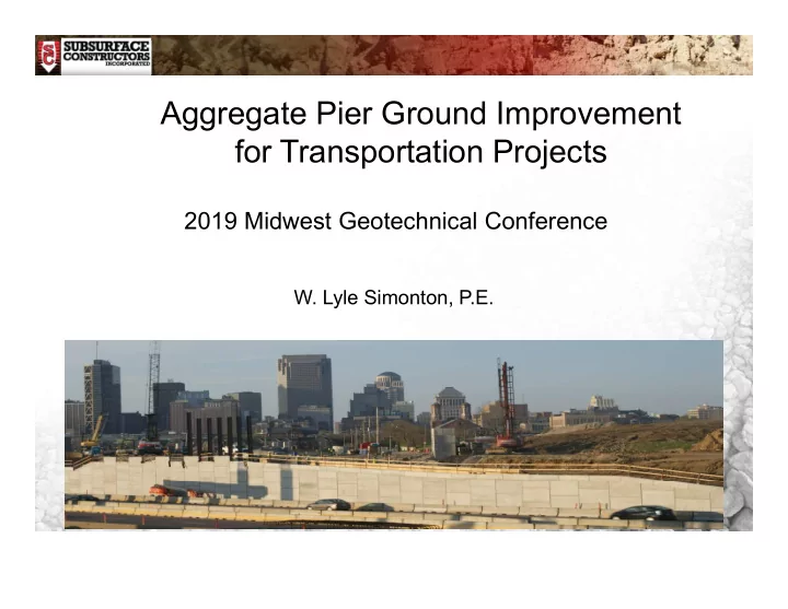

Aggregate Pier Ground Improvement for Transportation Projects 2019 Midwest Geotechnical Conference W. Lyle Simonton, P.E. www.subsurfaceconstructors.com
OVERVIEW Intro to Vibro Ground Improvement Objectives of Aggregate Pier/Stone Column Ground Improvement Examples of Transportation Projects (MO, IL, IN, OH, WI, OK, KS, soon to be CT) Specific Lessons Learned with Ground Improvement Specifications/Install/Testing www.subsurfaceconstructors.com
Vibro-Flot, Probe Hydraulic Motor or www.subsurfaceconstructors.com
Stratocaster Vibro Rigs • 40,000 lbs. of Crowd Force • 90,000 lb. Rig • 1st of these type of rigs in the USA www.subsurfaceconstructors.com
Excavator-Mount Mast System www.subsurfaceconstructors.com
Crane-Suspended Vibro www.subsurfaceconstructors.com
Basic Installation Techniques Dry Top Feed • Stable, Cohesive Soils • Pre-Drill or No Pre-Drill (hole diam., obstructions) Dry Bottom Feed • Collapsible Conditions • Stone Tremied to Bottom Wet Top Feed • Sand / Silty Sand Below WT • Liquefaction Mitigation (with stone) www.subsurfaceconstructors.com
Dry Top Feed Stone Columns (stable soil) www.subsurfaceconstructors.com
Dry Bottom Feed Stone Columns (collapsible soil) www.subsurfaceconstructors.com
Dry Bottom Feed Stone Columns I-69 Indiana Gohmann (GC) SR64 Over I-69 ILDOT Cedar Lake Rd www.subsurfaceconstructors.com E.S Wagner (GC) Round Springs, IL
Wet Top Feed Stone Columns (sand with fines) www.subsurfaceconstructors.com
www.subsurfaceconstructors.com
www.subsurfaceconstructors.com
DOT Projects www.subsurfaceconstructors.com
Objectives of Ground Improvement MSE Wall and Earth Embankment Support Bearing Pressure – Range based on wall height (5ksf typ) Settlement Criteria • Soil parameters critical (CPT preferred) • MSE wall supplier input • Define when/how it’s measured • May need to stage construction Liquefaction Mitigation • Understand limitations of GI techniques • Cannot substantially densify soils with fines >10% www.subsurfaceconstructors.com
Objectives of Vibro Ground Improvement Reinforce Soft to Med. Stiff, Cohesive/Fine-Grained Soils • Bearing pressure • Settlement • Not improving the soil strength • Modulus test / monitor settlement Densify Granular Soils • Bearing pressure • Settlement • Liquefaction mitigation • Substantial improvement proved with SPT/CPT www.subsurfaceconstructors.com
Design Considerations Primarily Bearing Pressure and Settlement Global Stability Liquefaction Mitigation Who Does the Design? Verification Program www.subsurfaceconstructors.com
Specification / Special Provision Missouri DOT – Aggregate Column Ground Improvement Experience – Work and Site Superintendent Aggregate Columns • Vibratory Compacted • Tamper Compacted Verification Program Plans indicate bearing pressure, settlement, global stability, etc. www.subsurfaceconstructors.com
Verification Program www.subsurfaceconstructors.com
New I-69 Design Build Indiana DOT New Interstate From Indianapolis to Evansville Current Design Build Work - 4 Sections • Section 1 – 13 miles – 5 Contracts • Section 2 – 29 miles – 7 Contracts • Section 3- 25 miles – 7 Contracts • Section 4 – 27 miles – 2 Contracts to Date Subsurface Constructors Work • Work on 4 - 5 Contracts (with 4 GCs) • Vibro Stone Columns • Wick Drains www.subsurfaceconstructors.com
Design-Build Project Approach State’s Geotechnical Engineer Makes General Recommendations Design-Build Team Develops Concepts • Exclusive Agreement with Specialty Contractor • Confidential Agreement with Specialty Contractor, But Not Exclusive Winning Team Develops Design • May Take Additional Geotech Info • Original Assumptions May Change • Put Ground Improvement Portion Out For Bid To Specialty Contractors www.subsurfaceconstructors.com
Section 3, Segments 12,13 Fred Weber / Jacobs Engineering I-69 Over CR900E • New Approach/Bridge Over Road • Significant Fill Height of Approach • Approach Embankment (Wick Drains) Twin Bridges Over Weaver/Vertrees Ditches • No New Embankment / MSE Walls • Bridge Abutment at Grade / Pile Foundations • Liquefaction-Induced Settlement www.subsurfaceconstructors.com
Twin Bridges Over Weaver/Vertrees Ditches Loose Sands, Sandy Loam To 10 ft to 18 ft Existing SPT N = 0 to 4 Original Proposal Was Deep Dynamic Compaction Additional Borings Taken, Team Decided on VSC Required Post-Treatment SPT N = 8 • Minimize Earthquake Induced Settlement • Designed VSCs = 30” diam, 15ft, 7ft spacing • Diff. Settlement in Transition Zone (further spacing) • Required 9-ft Spacing in Transition Zone www.subsurfaceconstructors.com
www.subsurfaceconstructors.com
BENT 2 Plans Sheets 2.5’ diam. VSC @ 7’ OC, except last row BENT 1 www.subsurfaceconstructors.com
Pre- and Post-Treatment SPT Tests Results Bent 1, Structure 33 N > 8 N > 8 www.subsurfaceconstructors.com
Pre- and Post-Treatment SPT Tests Results Bent 2, Structure 34 N > 8 N > 8 www.subsurfaceconstructors.com
www.subsurfaceconstructors.com
I-69 Over CR 900E Twin Bridges 55-Ft Long With MSE Wall Abutments MSE Wall Approx. 25-Ft High From Leveling Pad Liquefaction Analysis – OK Under Fill Global Slope Stability Requires Stone Columns www.subsurfaceconstructors.com
I-69 Over CR 900E www.subsurfaceconstructors.com
I-69 Over CR 900E www.subsurfaceconstructors.com
I-69 Over CR 900E Cross Section Stone Columns Work Plan: • Diam = 3 ft. • Spacing = 8 to 9 ft. • Depth = 37 to 41 ft. www.subsurfaceconstructors.com
www.subsurfaceconstructors.com
Lessons Learned Designing / Specifying Stone Columns What Is The Goal of Ground Improvement? Specialty Contractor May or May Not Perform the Design Specialty Contractor Should Be Consulted Verification of Performance Different Means and Methods to Construct www.subsurfaceconstructors.com
MSE Walls for MRB Approach 3 Large (up to 45ft) MSE Walls over I-70 in St. Louis Bearing pressure = 3,500psf to 7,100 psf Total Settlement = 2” Global Slope Stability • FS (undrained) = 1.2 • FS (drained) = 1.5 www.subsurfaceconstructors.com
MSE Walls for MRB Approach www.subsurfaceconstructors.com
Transition Columns Slope Stability Concern Moved MSE Wall * Somes slides/pics complements of Dan Brown and Associates www.subsurfaceconstructors.com
More Critical Global Stability MSE Wall Pushed Out; Issue became Apparent Enter DBA. www.subsurfaceconstructors.com
General X-Section when DBA Arrived Max Wall Elev. 497’ or 47ft Tall MSE Strap Zone Transition Columns Stone Columns Bedrock www.subsurfaceconstructors.com
Analysis of West MSE Wall Initially observed settlement of wall during construction (about 20ft of wall built) Subsurface recommends staged construction in thirds (1/3 total height of wall) Consultant analyzed global stability/soil strengths • FS(undrained) = 0.9 • FS (drained) = 1.6 Also observed some lateral movement of shorter wall where no stone columns installed www.subsurfaceconstructors.com
Wall pushed out. Movement occurred during installation of transition columns and stopped upon completion. www.subsurfaceconstructors.com
www.subsurfaceconstructors.com
Questions? www.subsurfaceconstructors.com
Recommend
More recommend