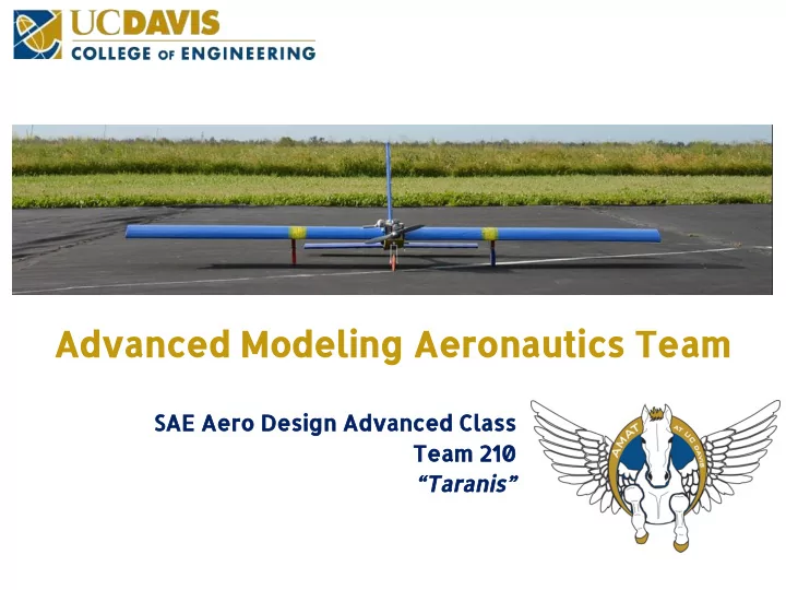

Advanced Modeling Aeronautics Team SAE Aero Design Advanced Class Team 210 “Taranis”
Advanced Modeling Aeronautics Team: # 210 Update Pictures! Agenda Overview • Project Planning & Management • Requirements Derivation • Vehicle Sizing • Propulsion • Trade Studies • Configuration Selection • Use of Materials • Stability & Control • Structure Analysis • Weight Buildup • Performance Analyses • Systems Testing & Integration •
Advanced Modeling Aeronautics Team: # 210 Overview • Powerplant: O.S. MAX AXII 2-Stroke 0.46 in 3 • Wingspan: 102.5 in • Foam Core Composite Wing Construction • Static Cargo Bay within Wing Spars 30.93 in 3 • Modular, rapid assembly • Short Construction Time • OEW: 13.70 lbf
Advanced Modeling Aeronautics Team: # 210 Project Planning Design Objectives • Engineering XLFR, MatLab, Python • Manufacturing Carbon Fiber Layup, 3D Printing • Wood Laser Cutting • Flight Test Control Surfaces • Drop Mechanism • Cost Mitigation •
Advanced Modeling Aeronautics Team: # 210 Visual Team Management Representation Fuselage Lead Wings Lead Empennage Lead Captain General Stability & Control Captain General Team General Team General Team Team Electronics Lead Captain Engine Lead Drop Mechanism Lead Landing Gear
Advanced Modeling Aeronautics Team: # 210 Requirements Derivation ● Maximize Flight Score ○ Assumptions ■ Low Accuracy ■ 8 lbf OEW ○ Payload ■ Static vs. Dynamic ■ Accuracy ● Ease of Transport ● Manufacturability ● Takeoff Distance ● Maneuverability
Advanced Modeling Aeronautics Team: # 210 Vehicle Sizing ● Maximize Lift ● Power Constraint ● Minimize Drag ● Structural Limitations ● Effectiveness of control surfaces ● Manufacturing Process
Advanced Modeling Aeronautics Team: # 210 Propulsion Reliable • Ogawa Seisakusho • (O.S.) MAX AXII 2-Stroke 12x6 APC Propeller • Static Thrust: 6.0 lb f • 12000 RPM Static • Dynamic thrust model •
Advanced Modeling Aeronautics Team: # 210 Trade Studies Wings: Straight v. Tapered Airfoils:CH-10, Clark Y, Eppler 214, CR 1, Selig Tail: H-Tail v. Conventional v. V-Tail NACA 12, NACA 14 Landing Gear: Tricycle v. Taildragger NACA 12 Tricycle Design Selig 1223
Advanced Modeling Aeronautics Team: # 210 Configuration Selection Feature Reasoning Conventional Tail Reliable, stable configuration • High Aspect Ratio Wing Superior lift to drag ratio • Allows for internal cargo bay & contiguous spar • Rectangular Mid Wing Places AC above CG for lateral stability • Simple, quickly repeatable structure • Allows for lower drag zero-incidence roll • Tricycle Landing Gear Forward gear balances facilitates CG balance • Improved consistency & reliability over • Single Puller Engine multiple engine configuration Forward engine balances CG with tail •
Advanced Modeling Aeronautics Team: # 210 Use of Materials Material 3K Bi-Directional Balsa Wood/ Red Oak Polystyrene Foam Carbon Fiber/Epoxy Basswood Use Fuselage, Wings, Fuselage, Firewall Wings Empennage Empennage Reasoning 1 Layer at 0 ° /90 ° Lightweight Good Large ● ● ● ● Minimize weight Easily properties in availability ● ● Structural accessible and tension and from donor. ● improvement machinable compression Easily shaped ● Material used Replaceable High density to desired ● ● ● from previous -------------------- for CG shape. Vacuum bag Strong balancing Good bending ● ● ● lay-up resistance to strength Cutting/Sanding bending Provide ● ● for lightening curvature for ● and finishing composite lay-up
Advanced Modeling Aeronautics Team: # 210 Stability & Control 7.55 in 6 in 8 in 22 in Main Horizontal Vertical Wing Stabilizer Stabilizer Aspect Ratio 6.83 3.5 2.075 Control Surface Span [in] 15 17.25 Each 21 Control Surface Chord [in] 5 4.27 4.27
Advanced Modeling Aeronautics Team: # 210 Aircraft Structures & Methods • Laser Cutting • Airfoil Stencils/Tail Ribs/Fuselage • Accurate and easy assembly • Carbon Fiber Vacuum Bag Layup • Fuselage: balsa-carbon composite • Flat fuselage panels for simple layups • Continuous fabric for drapability of wings • 3D Printing • Plastic is suitable for expected loads • Used for Landing Gear and Fairings • Polystyrene Foam • Hotwire and Drill Shaping
Advanced Modeling Aeronautics Team: # 210 Stress Analysis: Empennage, Fuselage, and Wing Empennage Wind Gust Load Factor at bank Balsa v Basswood Base • angle 15 o Carbon Fiber • No Wind Gust ~ 1.0 Reinforcement against bending 25% Cruise Speed ~ 1.5 Fuselage 75% Cruise Speed ~ 3.0 Failure of Balsa to take • thrust from Engine Needed higher integrity • wood for support Wings Designed against high • loading and gusts with high Factor of Safety
Advanced Modeling Aeronautics Team: # 210 Performance Verification • Testing used to verify thrust numbers Propeller Selection • based upon Dynamic Thrust
Advanced Modeling Aeronautics Team: # 210 Weight Management 10.33 Predicted Weight: 10.33 lb Actual Weight: 13.70 lb
Advanced Modeling Aeronautics Team: # 210 Advanced Class Flight Systems Altimeter FPV Camera Pitot Tube Battery Ground Station Drop Servo
Advanced Modeling Aeronautics Team: # 210 Questions?
Recommend
More recommend