SUPERPARAMAGNETIC CORE/SHEATH COMPOSITE NANOFIBERS VIA COAXIAL - PDF document
18 TH INTERNATIONAL CONFERENCE ON COMPOSITE MATERIALS SUPERPARAMAGNETIC CORE/SHEATH COMPOSITE NANOFIBERS VIA COAXIAL ELECTROSPINNING B.W. Ahn*, M.H. Hahn, T.J. Kang Department of Materials Science and Engineering, Seoul National University,
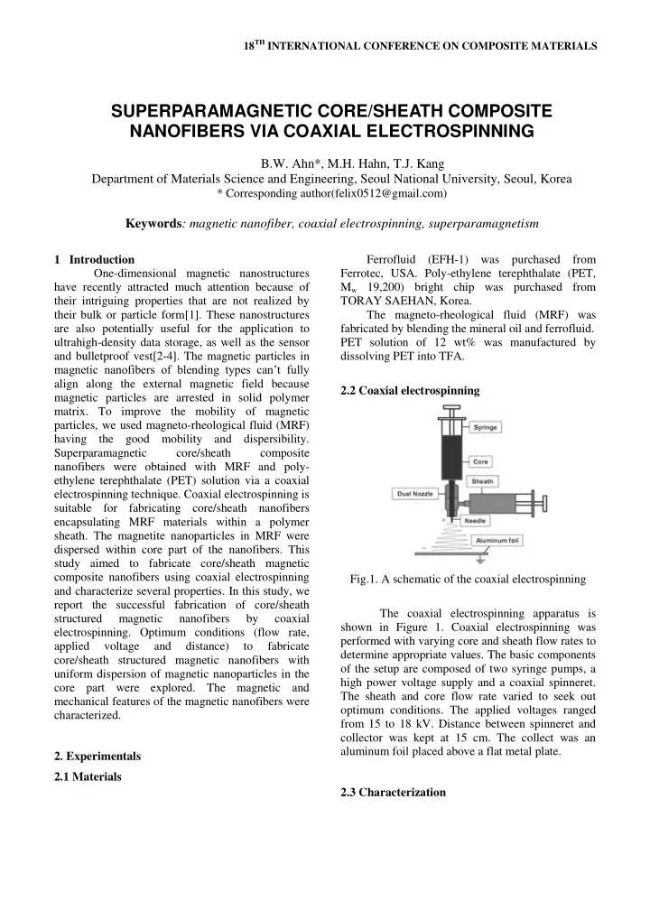
18 TH INTERNATIONAL CONFERENCE ON COMPOSITE MATERIALS SUPERPARAMAGNETIC CORE/SHEATH COMPOSITE NANOFIBERS VIA COAXIAL ELECTROSPINNING B.W. Ahn*, M.H. Hahn, T.J. Kang Department of Materials Science and Engineering, Seoul National University, Seoul, Korea * Corresponding author(felix0512@gmail.com) Keywords : magnetic nanofiber, coaxial electrospinning, superparamagnetism 1 Introduction Ferrofluid (EFH-1) was purchased from One-dimensional magnetic nanostructures Ferrotec, USA. Poly-ethylene terephthalate (PET, have recently attracted much attention because of M w 19,200) bright chip was purchased from their intriguing properties that are not realized by TORAY SAEHAN, Korea. their bulk or particle form[1]. These nanostructures The magneto-rheological fluid (MRF) was are also potentially useful for the application to fabricated by blending the mineral oil and ferrofluid. ultrahigh-density data storage, as well as the sensor PET solution of 12 wt% was manufactured by and bulletproof vest[2-4]. The magnetic particles in dissolving PET into TFA. magnetic nanofibers of blending types can’t fully align along the external magnetic field because 2.2 Coaxial electrospinning magnetic particles are arrested in solid polymer matrix. To improve the mobility of magnetic particles, we used magneto-rheological fluid (MRF) having the good mobility and dispersibility. Superparamagnetic core/sheath composite nanofibers were obtained with MRF and poly- ethylene terephthalate (PET) solution via a coaxial electrospinning technique. Coaxial electrospinning is suitable for fabricating core/sheath nanofibers encapsulating MRF materials within a polymer sheath. The magnetite nanoparticles in MRF were dispersed within core part of the nanofibers. This study aimed to fabricate core/sheath magnetic composite nanofibers using coaxial electrospinning Fig.1. A schematic of the coaxial electrospinning and characterize several properties. In this study, we report the successful fabrication of core/sheath The coaxial electrospinning apparatus is structured magnetic nanofibers by coaxial shown in Figure 1. Coaxial electrospinning was electrospinning. Optimum conditions (flow rate, performed with varying core and sheath flow rates to applied voltage and distance) to fabricate determine appropriate values. The basic components core/sheath structured magnetic nanofibers with of the setup are composed of two syringe pumps, a uniform dispersion of magnetic nanoparticles in the high power voltage supply and a coaxial spinneret. core part were explored. The magnetic and The sheath and core flow rate varied to seek out mechanical features of the magnetic nanofibers were optimum conditions. The applied voltages ranged characterized. from 15 to 18 kV. Distance between spinneret and collector was kept at 15 cm. The collect was an aluminum foil placed above a flat metal plate. 2. Experimentals 2.1 Materials 2.3 Characterization
The morphology was observed by using 2 9 P r E High Resolution-Transmission Electron Microscopy 3 16 R e (HR-TEM, JEOL JEM-3010) and Field Emission- where, P is the applied force, is the indentation Scanning Electron Microscope (FE-SEM, JEOL depth, and R e is the equivalent radius for a indenter JSM-6700F). The mechanical properties were in contact. R e is given by analyzed by using Atomic Force Microscope (AFM, Park SYSTEMS XE-100). Lastly, magnetic behavior 2 R R t f R was measured using Superconducting Quantum e R R t f Interference Device magnetometer (SQUID, where, R t is the indenter tip radius (25 nm) and R f Quantum Design MPMS XL5). is the radius of the nanofiber. R f was determined by analysis of the height profile using AFM. Every measurement was done with the nanofibers which diameter was about 600±50 nm. The elastic modulus of nanofiber E f is given by f ( 1 2 ) E E f r where, f is the Poisson’s ratio of the nanofiber (0.33). 3. Results and discussion 3.1 Morphology Fig.2. Schematic diagrams of (a) nanoindentation test and (b) nanoindentation test with a magnetic field generator. The mechanical properties of core/sheath magnetic composite nanofibers were measured using nanoindentation. The samples for this test were Fig.3. A SEM image of MRF/PET nanofiber. collected on the Si wafer by coaxial electrospinning. The moduli are calculated using the Hertz theory from the load-indentation depth data[5]. The elastic SEM images of MRF/PET nanofibers were modulus of one nanofiber was measured by shown in Figure 3. The mean diameter of these nanoindentation method (Fig..2). A nanoindentation nanofibers was 500~600 nm (Figure 4). For tip (pyramidal shape, Park system, Korea) and fabricating continuous core/sheath magnetic magnetic field generator (-0.03 ~ +0.03 T, Park composite nanofibers, various parameters should be system, Korea) were installed to atomic force controlled such as applied voltage, solution viscosity, microscope (AFM, XE-100, Park system, Korea). concentration, and flow rate etc. Among them, the We observed the change in elastic modulus of one immiscibility of two liquids is the key factor in nanofiber when the external magnetic field was manufacturing the core/sheath magnetic composite applied. The elastic modulus of nanofibers was nanofibers. We prepared core/sheath magnetic calculated according to the following equations. The nanofiber successfully with control of several relative elastic modulus E r is given by parameters (Fig. 5). The mass ratio of mineral oil
PAPER TITLE and ferrofluid was 1.5 :1. The flow rate of core and coercivity (12.32 Oe) and negligible remnant sheath fluid were 7 and 5 ㎕ /min, respectively. magnetization at zero field (0.42 emu/g). It is known that superparamagnetism is often observed for magnetic nanoparticles with sizes less than 10 nm. It also suggested that bulk Fe 3 O 4 shows ferromagnetism because lager size domain of the bulk form induce alignment of magnetic dipole moments to be parallel for minimizing thermodynamic internal energy[6,7]. However, it is well known that even ferromagnetic materials show superparamagnetic behavior at room temperature when the particles size becomes dozens nanometers[7]. Therefore, the superparamagnetic behavior of each magnetic nanofiber may be related to the small particle size (5~10 nm). This critical diameter typically depends on the material Fig.4. Diameter distribution of MRF/PET nanofibers. properties. The saturation magnetizations, M s , were 17.10 and 10.80 emu/g. It was considerably smaller than M s of bulk iron (330 emu/g). This is general phenomenon of magnetic nanomaterials[6]. Figure 7 shows susceptibility of MRF/PET nanoweb as a function of magnetic field intensity. Fig.5. A TEM image of MRF/PET nanofiber. 3.2 Magnetic properties Fig.7. Susceptibility of MRF/PET nanofibers. 3.3 Nanoindentation Figure 8 showed that loading and unloading curves for single core/sheath magnetic composite nanofiber with and without the magnetic field applied. When the external field applied, the loading and unloading curves shifted upward, indicating a significant increase in modulus of the sample. The Fig.6. A magnetic curve of MRF/PET nanofibers. improvement of modulus is thought to be related with the strong dipole-dipole interaction between magnetic nanoparticles occurred by alignment of Magnetic curves of MRF/PET nanofibers at magnetic nanoparticles with help of the great fluidity room temperature are shown in Figure 6. The of the MRF. Table 1 presented mechanical hysteresis loops of each nanofiber were that of a properties calculated from Figure 8. typical superparamagnetic material with small 3
Recommend


More recommend
Explore More Topics
Stay informed with curated content and fresh updates.