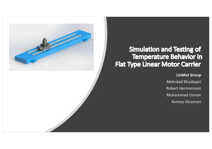

Si Simulation and Testing of of Te Temperature Behavior in in Fl Flat Typ ype e Linea ear Mot Motor or Carrier er LinMot Group Mehrdad Khodayari Robert Hermansson Muhammad Usman Kimmo Hirvonen
Motor moving in real life Motor running with rapid movement* *This cycle was not used in the experimental tests. It is just for presenting the motor in action.
Siemens Linear Motor L-1FN3 with SINUMERIK Control Working principle and Control • The magnetic flux of coils and permanent magnets generate tangential and normal forces. • Benefits: Fast, powerful and precise motor • More sensitive to various force disturbances • Driven by a PWM-modulated three-phase bridge • Controlled with a standard SINUMERIK 840D sl CNC control Purpose Simulation and Testing of Temperature Behavior in • Flat Type Linear Motor Carrier https://www.youtube.com/watch?v=0_QBl6-_jJU
Research problem • Problem of the linear motors is heat generation Limits the performance, affects the accuracy • Our research Test and Simulate the temperature behavior of Flat Type linear motor Results could be used for: Predict the temperature behavior of flat type linear motor in other applications • Simulation model and methods could be used to study the temperature behavior in • other similar type systems For further study of how different loads, working cycles and water-cooling system • affect the temperature behavior
Methods for experimental research Weight Section Temperature measurement on • Coolant Water top of the carriage Inlet External load added to the • Thermistor carriage Coolant water Water cooling not used in our • outlet research PT-100 Primary Coil Section
Duty cycle Displacement in each step: 150mm Velocity: 30 000 mm/min Acceleration: 30m/s^2
Simulation methods and results A simple Simulink model consisting of power losses equations, which takes current data as input and outputs power losses to heat the motor coils.
Simulation results • Simulink average heat power loss =49.86 W The graph shows the electric power losses with time in heating the coils.
FEM analysis and results Steady state heat transfer FEM analysis with Solidworks: • Heat power of 50 W applied to the carrier bottom surface ! Air convection coefficient of 11 • " # $ assumed for carrier surface Temperature at the carrier surface reaches 57 ℃ maximum
Experimental results Continuous duty cycle: Total mass 15.6 kg • Velocity 30000 mm/min • Acceleration 30 m/s^2 • • 150 mm movements 0.2 s break between • movements Results Starting temperature 23 ℃ • Final temperature 57 ℃ • Cycle duration 1h 42min •
Comparison of the experimental and simulation results Results are really close to each other with the maximum temperature of 57 ℃ •
Special thanks to: Aalto University : Petri Kuosmanen and Panu Kiviluoma Siemens: Juha Meriaho and Pasi Laari Heidenhein: Esa Härkönen
Recommend
More recommend