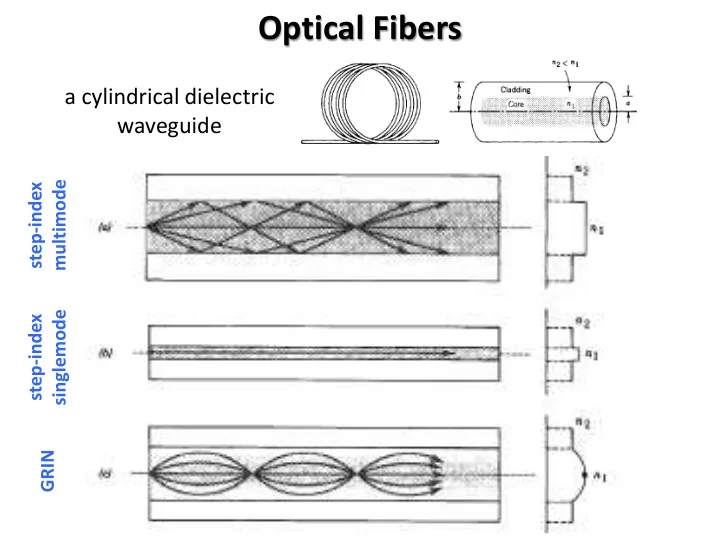

Optical Fibers a cylindrical dielectric waveguide multimode step-index singlemode step-index GRIN
Modes in Optical Fibers Cartesian coordinates 𝜖 2 𝐹 𝑦, 𝑧 + 𝜖 2 𝐹 𝑦, 𝑧 + 𝑜 2 𝜕 2 𝑑 2 − 𝛾 2 𝐹 𝑦, 𝑧 = 0 𝜖𝑦 2 𝜖𝑧 2 𝑭 𝑦, 𝑧, 𝑨, 𝑢 = 𝐹 𝑦, 𝑧 𝑓 𝑘 𝜕 𝑢 − 𝛾 𝑨 Cylindrical coordinates 𝜖 2 𝐹 𝑠, 𝜚 𝜖 2 𝐹 𝑠, 𝜚 + 𝑜 2 𝜕 2 + 1 𝜖𝐹 𝑠, 𝜚 + 1 𝑑 2 − 𝛾 2 𝐹 𝑠, 𝜚 = 0 𝜖𝑠 2 𝑠 2 𝜖𝜚 2 𝑠 𝜖𝑠 𝑭 𝑠, 𝜚, 𝑨, 𝑢 = 𝐹 𝑠, 𝜚 𝑓 𝑘 𝜕 𝑢 − 𝛾 𝑨
Solutions 𝐹 𝑠, 𝜚 = 𝑣 𝑠 𝑓 𝑘 𝑚 𝜚 𝑓 𝑒 2 𝑣 𝑜 2 𝜕 2 𝑑 2 − 𝛾 2 − 𝑚 2 𝑒𝑠 2 + 1 𝑒𝑣 𝑒𝑠 + 𝑠 2 𝑣 = 0 𝑠 2 ≡ 𝑜 𝑑𝑝2 𝜕 2 − 𝛾 2 𝑙 𝑈 𝑑 2 𝛿 2 ≡ 𝛾 2 − 𝑜 𝑑𝑚2 𝜕 2 𝑑 2 Boundary conditions for 𝐹 𝑨 , 𝐼 𝑨 , 𝐹 𝜚 , 𝐼 𝜚
Graphical Representation
Power Confinement Fraction of the power propagating inside the core against the V-number. Right above the cut-off, very little power is inside the core. As the core diameter increases, the power of the mode becomes confined inside the core.
Optical Attenuation 0.16 dB = (3.6 %) 1 𝑒𝐶 = −10 𝑚𝑝 𝑈
Dispersion • modal dispersion • material dispersion • waveguide dispersion
Numerical Aperture 𝑜 𝑑𝑝2 − 𝑜 𝑑𝑚2 𝑂𝐵 = 𝑜 0 sin 𝜄 0 = V-number 𝑊 = 2𝜌 𝑏 𝑜 𝑑𝑝2 − 𝑜 𝑑𝑚2 = 2𝜌 𝑏 single-mode operation 𝜇 𝜇 𝑂𝐵 𝑊 < 2.405 Number of Guided Modes in an Optical Fiber 𝑁 = 4 𝜌 2 𝑊 2
End Coupler 𝔽 𝑗𝑜 𝑭 𝛽 𝔽 𝑗𝑜 𝑦, 𝑧 = 𝑏 𝛽 𝑭 𝛽 𝑦, 𝑧 input field decomposed into modes of the guide 𝛽 2 ∗ 𝑒𝐵 𝔽 𝑗𝑜 . 𝑭 𝛽 Overlap Integral : fraction 𝜃 𝛽 = 2 𝑒𝐵 𝑭 𝛽 2 𝑒𝐵 of coupled power into each mode 𝔽 𝑗𝑜
Recommend
More recommend