ODOT GUE -513-08.65 SR-513 o ve r I -70: Curve s, T ruc ks, a nd - - PowerPoint PPT Presentation

odot gue 513 08 65
SMART_READER_LITE
LIVE PREVIEW

ODOT GUE -513-08.65 SR-513 o ve r I -70: Curve s, T ruc ks, a nd - - PowerPoint PPT Presentation

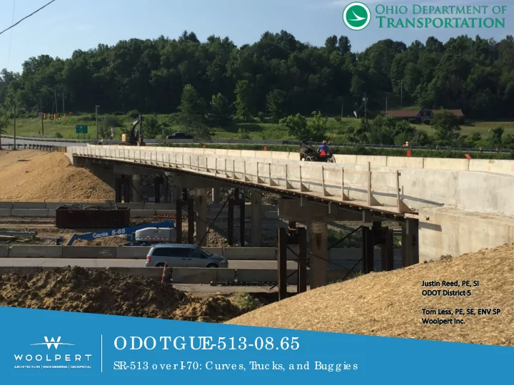
ODOT GUE -513-08.65 SR-513 o ve r I -70: Curve s, T ruc ks, a nd Bug g ie s GUE -513-08.65 ODOT - Project Background Reasoning / funding: This bridge was noted to have worsening deck conditions forcing it from a GA of 6A to 5A most


slide-1
SLIDE 1

ODOT GUE

  • 513-08.65

SR-513 o ve r I

  • 70: Curve s, T

ruc ks, a nd Bug g ie s

slide-2
SLIDE 2

GUE

  • 513-08.65

ODOT - Project Background Reasoning / funding:

  • This bridge was noted to have worsening deck conditions forcing it from a GA of 6A to 5A most

recently.

  • Increasing ADTT demands in the eastern portion of District 5, this was just reasoning to

investigate HL-93 load capacity vs HS-20. Therefore; increased funding was allocated to this site in accordance with the associated need.

  • Being a structure within a 4° 45’ curve, a grid analysis would be required as part of the project as

per AASHTO Section 4.6.1.2.4b. To avoid must meet:

  • Girder lines concentric

  • Bearing lines not skewed more than 10 degrees

X (19° 32’ 07”)

  • Stiffness of girders is similar

  • Arc span / radius < 0.06 radians

 (0.059 rad. actual)

District 5 standards / challenges:

1. With the superstructure being replaced, the new beam depths were to be compared to those necessary to obtain a minimum 16’-6” vertical clearance. Up from 16’-1” existing. 2. The piers columns being in good general condition, investigate the use of portions of existing substructures combined with abutment widening. 3. M.O.T. for this project was requested to be signalized closing 1-lane of a 2-lane highway. 4. Semi-integral abutment details and scupper details.

slide-3
SLIDE 3

ODOT

  • 1a & 1b

Semi-integral bridges are preferred per ODOT BDM section 205.9, but should not be used in combination with a curved structure without special considerations. Design and draft provisions to account for necessary details when using this style of abutment with a curved

  • bridge. A geowall was utilized to provide the necessary

clearance behind the diaphragm and give freedom of

  • movement. Also, District preferred, sleeper slabs with

armorless free expansion joints were utilized at the ends

  • f approach slabs.
slide-4
SLIDE 4

ODOT

  • 3

High importance was placed on bridge deck drainage versus minimizing the use of scuppers per BDM section 209.3. Therefore project customized scuppers were detailed to fit this proposed framing plan and used throughout the bridge.

slide-5
SLIDE 5

GUE

  • 513-08.65 De sig n - Ove rvie w

Complicating Factors:

  • Survey Multiple Data Sets
  • Geometrics & MOT
  • Vertical Sag Curve
  • Horizontal Curve
  • Intersections
  • Traffic Design
  • Amish Buggies
  • Trucks and Oil & Gas Traffic
  • Ramps & Intersections
  • Vertical Curves
  • Sight Distance
  • Structural Design
  • Horizontally Curved Girders
  • Part-Width Construction
  • Temporary Supports
  • Deck Pour Sequencing
slide-6
SLIDE 6

GUE

  • 513-08.65 De sig n - Surve y

Survey

  • ODOT Provided Aerial Lidar
  • Woolpert Ground Lidar & Trad.
  • Meshed Both together with control
  • Full 3D Bridge Extraction
  • Top deck surface to bottom deck surface allowed us to verify existing
  • verlay thicknesses
  • Detailed Lidar used to pinpoint vertical clearance – found to be better than

listed which reduced the need for profile raising

slide-7
SLIDE 7

GUE

  • 513-08.65 De sig n - Ove rvie w

SR-513 Roadway Criteria

  • Design exceptions
  • K value (79 vs. 115)
  • Superelevation rate (6% vs. 7.7%)
  • 2,670 Design ADT, 13% Trucks
  • Rural Major Collector
  • Design/Legal Speed 55 mph
  • Maintaining Horizontal/Vertical Geometry
  • Minimizing superstructure depth prevented need for profile raising
  • Increasing superelevation would require additional raising
  • Hills on either side of the interchange along SR-513, concerns with

truck stopping, sight distance and advanced warning

  • Practical Design – reaching normal design K and super would increase

project size and cost without significantly improving functional conditions

slide-8
SLIDE 8

GUE

  • 513-08.65 De sig n - Ge o me tric s
slide-9
SLIDE 9

GUE

  • 513-08.65 De sig n - I

nte rse c tio ns

Northern Intersection

  • 6-Legs
  • Access to Gas Station
  • County Highway Dept. on Bridgewater

Southern Ramp Intersection

  • Truck Turning Movements
  • Sight Distance
slide-10
SLIDE 10

GUE

  • 513-08.65 De sig n – I

nte rse c tio n MOT

Phase 1

slide-11
SLIDE 11

GUE

  • 513-08.65 De sig n – I

nte rse c tio n MOT

Phase 2

slide-12
SLIDE 12

GUE

  • 513-08.65 De sig n – I

nte rse c tio n MOT

Phase 1

slide-13
SLIDE 13

GUE

  • 513-08.65 De sig n – I

nte rse c tio n MOT

Phase 2

slide-14
SLIDE 14

GUE

  • 513-08.65 De sig n – T

ra ffic De sig n

  • Traffic Analysis
  • Need to account for both trucks at 55 mph and Amish Buggies at much

slower speeds

  • Synchro Model Used
  • Amish Buggies modeled at 15 mph
  • Resulted in longer clear times under all red conditions
slide-15
SLIDE 15

GUE

  • 513-08.65 De sig n – T

ra ffic De sig n

  • Northern Intersection Temporary Signals
slide-16
SLIDE 16

GUE

  • 513-08.65 De sig n – Struc tura l De sig n
  • SR-513 over IR-70
  • Curved 4-Span Bridge (60’-11.75”, 2 @ 86’-9”, 60’-10.75”)
  • Skewed 19° 32’ 07” to reference chord
  • Composite on curved rolled steel beams
  • R = 1206.23 ft
  • Minimum Girder R = 1185.48 ft
  • Dc = 4⁰ 45’ 00”
  • All crossframes and girders radial
  • Vertical Sag Curve
  • Part-width construction, including pier caps
slide-17
SLIDE 17

GUE

  • 513-08.65 De sig n – Struc tura l De sig n
slide-18
SLIDE 18

GUE

  • 513-08.65 De sig n – Struc tura l De sig n
  • Note – no fence used as it would cause sight distance issues at the ramps,

waiver requested and approved through ODOT OSE

slide-19
SLIDE 19

GUE

  • 513-08.65 De sig n – Struc tura l De sig n
slide-20
SLIDE 20

GUE

  • 513-08.65 De sig n – Struc tura l De sig n
slide-21
SLIDE 21

GUE

  • 513-08.65 De sig n – Struc tura l De sig n
  • Structure Feasibility Study Performed
  • Additional existing overlay and higher existing vertical clearance

verified from LiDAR helped minimize profile increase.

  • Existing beams = 36WF194, new are W27x307 Grade 50 beams.
  • Cross slope at 6% with widened structure and larger exterior beam
  • ffset reduced vertical clearance.
  • Overall providing 16’-8 ½” clearance, up from existing 16’-0 ½”.
  • Total profile adjustment of 2 ½” to account for construction tolerance

and future overlays above 16’-6” required. All within bridge limits.

  • Other options were a W24x335 with minimal profile raise or W30x261

with 5 ½” raising, but were eliminated as less economical.

  • Initial beam design by V-load and girder line analyses
  • Verified by finite element analysis in final design (Grillage+), led to 10%

increase for curvature effects.

  • AISC and NSBA design guidelines and fabricators consulted for

constructability.

slide-22
SLIDE 22

GUE

  • 513-08.65 De sig n – Struc tura l De sig n
  • Girder Line Modeling with V-load
  • Uses standard AASHTO LLDF
  • Can be done in minimal time, not a complicated analysis
  • Use results to populate a V-Load analysis spreadsheet or hand calculation,

and iterate with a target utilization ratio (1.00 – anticipated V-Load increase)

  • Typically produces good results for dead load approximations for

noncomposite and composite bridges with radial crossframes or bracing

  • Live load can be much more variable based on lateral stiffness, geometry,

and resulting intermittent influence surface

  • Typically a good method for preliminary engineering purposes
  • Essentially, straighten girder and analyze based on true length as a straight

member, then apply external forces to induce resultant internal forces corresponding to the curved structure under vertical loads

  • From past projects, results have been very close to MIDAS Civil or other FEM

for larger radii, say R > 1000-ft

  • Per AASHTO Section C4.6.2.2.4 has a number of limitations which do not

qualify for required analysis methods for curved structures and may underestimate deflections, reactions, twist

slide-23
SLIDE 23

GUE

  • 513-08.65 De sig n – Struc tura l De sig n
  • 2D+ Grillage Analysis/Limited 3D Analysis
  • Similar to standard grillage, but with multiple sets of nodes with rigid links

(master-slave)

  • Beams/girders are modeled using beam elements then rigid linked nodes

modeling the deck plates and nodes for crossframe members in 3D

  • Provides an accurate distribution of live loads through influence surface
  • Lateral stiffness of crossframes and deck are modeled using this approach
  • Internal forces are captured using this approach, appropriate for curved

girder design

  • Seventh degree of freedom included for warping effects
slide-24
SLIDE 24

GUE

  • 513-08.65 De sig n – Struc tura l De sig n
  • Full 3D Analysis
  • Similar to the Grillage+, but the beam is split into plate elements for each

flange and web, in addition to plates for the deck

  • Provides an accurate distribution of live loads through influence surface
  • Lateral stiffness of crossframes and deck are modeled using this approach
  • Internal forces are captured using this approach, appropriate for curved

girder design

  • Effects of tension-field action can be captured for shear
  • Girder/Beam rotations can be explicitly extracted – very important for

construction cases in highly curved members

slide-25
SLIDE 25

GUE

  • 513-08.65 De sig n – Struc tura l De sig n
  • Curved Beams/Girders
  • Plate girders have curves cut from larger flat sheets
  • Beams are always produced as straight members from mill, then curved.
  • Two primary methods
  • Mechanical rolling using sets of rollers to gradually deform beams
  • Heat curving which is performed by placing the beam on its side on

blocking (similar to when producing vertical camber) and applying heat to locally deform the beam.

  • Mechanical methods are dependent on fabricator equipment for segment

weight and length to avoid crushing rollers and supports.

  • Fewer limitations on heat curving and ODOT CMS 513 requires heat

curving.

  • Beam availability was considered, both from number of suppliers and

rolling frequency.

  • Interaction between vertical and horizontal camber may need to be

considered per AASHTO

slide-26
SLIDE 26

GUE

  • 513-08.65 De sig n – Struc tura l De sig n
  • Curved Beams/Girders
  • No-Load Fit Used
  • When determining camber, if Radii is less than 1000-ft need to account

for additional camber from settling of the curved structure per AASHTO 6.7.7.3. Not required here.

slide-27
SLIDE 27

GUE

  • 513-08.65 De sig n – Struc tura l De sig n
  • Temporary support towers originally used one tower with compression and

tension connection (bearings & tension rods)

  • After discussion with ODOT, added a second tower for redundancy.
  • Order of preference: Compression -> Tension -> Shear
slide-28
SLIDE 28

GUE

  • 513-08.65 De sig n – Struc tura l De sig n
  • Temporary Supports – As Designed
slide-29
SLIDE 29

GUE

  • 513-08.65 De sig n – Struc tura l De sig n
  • Temporary Supports – As Designed, Stage 1
slide-30
SLIDE 30

GUE

  • 513-08.65 De sig n – Struc tura l De sig n
  • Stage 2
slide-31
SLIDE 31

GUE

  • 513-08.65 De sig n – Struc tura l De sig n
  • Stage 3
slide-32
SLIDE 32

GUE

  • 513-08.65 De sig n – Struc tura l De sig n
  • Stage 4
slide-33
SLIDE 33

GUE

  • 513-08.65 De sig n – Struc tura l De sig n
  • Actual temporary

shoring used similar design but some differences

  • Larger sections –

simplified design

  • Reduced cross

bracing

  • Bracing used

bolted moment connections with H shapes rather than angle X-brace

  • Jacks at bottom
  • f towers

instead of top

slide-34
SLIDE 34

GUE

  • 513-08.65 De sig n – Struc tura l De sig n
slide-35
SLIDE 35

GUE

  • 513-08.65 De sig n – Struc tura l De sig n
slide-36
SLIDE 36

GUE

  • 513-08.65 De sig n – Struc tura l De sig n
slide-37
SLIDE 37

GUE

  • 513-08.65 De sig n – Struc tura l De sig n
slide-38
SLIDE 38

GUE

  • 513-08.65 De sig n – Struc tura l De sig n
slide-39
SLIDE 39

GUE

  • 513-08.65 De sig n – Struc tura l De sig n
slide-40
SLIDE 40

GUE

  • 513-08.65 De sig n – Struc tura l De sig n
slide-41
SLIDE 41

GUE

  • 513-08.65 De sig n – Struc tura l De sig n
slide-42
SLIDE 42

GUE

  • 513-08.65 De sig n – Struc tura l De sig n
slide-43
SLIDE 43

Que stio ns?