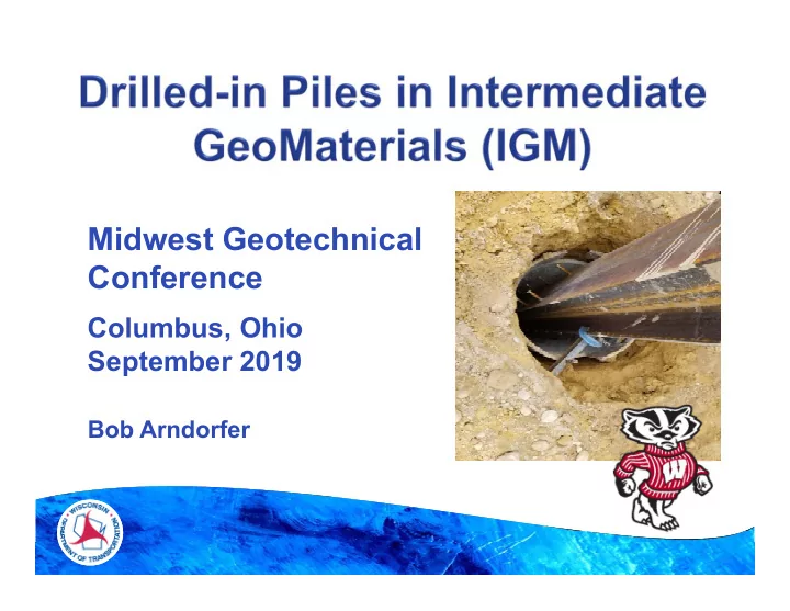

Midwest Geotechnical Conference Columbus, Ohio September 2019 Bob Arndorfer
AASHTO Definitions: Cohesive IGMs - Exhibit Unconfined Compression Strengths Between 10-100 ksf Cohesionless IGMs - Exhibit Blow Counts (N) Greater Than 50 Blows/Foot Using Standard Penetration Test 2
Hole is Drilled (Pre-bored) Into the IGM Material and Bottom is Cleaned H-Pile Is Placed Into Hole – No Driving (Seated) Hole Is Backfilled With Concrete Pile Extends Up Into Abutment Is the Resulting Deep Foundation Member a Shaft or a Pile? 3
WisDOT Experience with IGM Varies Codes Provide Limited Guidance on Design Methodology/Pile Capacity in IGM Materials Project Used Load Test to Verify Design Assumptions For Drilled-in Piles Lead to a Methodology Used to Design Drilled- in Piles in IGM Material Help Eliminate Some Common Pile Installation Issues In These Situations Goal – Save Money 4
WisDOT Often Designs MSE Walls Around Abutments Reduce Bridge Span Lengths Support Abutments on Piles Through MSE Backfill Install Piles Prior to Wall Construction IGM Materials Make Pile Length Estimates Difficult Difficult Driving Often Leads to Pile Alignment Issues What About Installing Pre-bored/Backfilled Piles Into the Very Dense IGM? 5
Alternative Foundations? Why Not Use Spread Footings? Why Not Use Drilled Shafts? Will Address Those Later Proper Design Methodology – Shaft or Pile? What Corresponding Resistance Factor? Cost Effective to Conduct a Pile Load Program? 6
7
Site Has High-strength Till Soils Consultant-Designed Project Multi-Year Construction Project Had Enough Lead Time to Accommodate Load Test Program Was an Adjacent, On-going Project We Could Add Load Test Program to Results From Load Test Incorporated Into Project Plans (Pre-Letting) 8
9
Chippewa River 10
Chippewa River 11
Chippewa River 12
Driven H-Piles Using Modified Gates: Resistance Factor of 0.50 Driven H-Piles Using Pile Driving Analyzer: Resistance Factor of 0.65 Drilled Shafts: Resistance Factor 0.35-0.5 (No Load Test) Bored H-Piles With Static Load Test: Resistance Factor of 0.8 (Load Test) Resistance Factor of 0.8 (Shaft Spacing) 13
Sometimes Piles Run Very Long (Increased Cost and Times), or Very Short (Creating a Lateral Resistance Concern) Difficult to Achieve Necessary Alignment Above Driven Elevation – Often Not Aware of This Until After Hammer Leads are Removed Adjacent Bridge Experienced Both of These Issues 14
Larger Diameter/Conflicts With MSE Wall Requires Slightly Longer Bridge Lower Resistance Factor (No Load Test), Resulting in Deeper Shafts Secant Walls Also Considered – High Cost 15
Multi-span Bridges: WisDOT Typically Does Not Use Spread Footings on MSE Walls Would Require Expensive Full-retaining Abutments and Wings Instead of MSE Wall Early Cost Estimate Indicated Pre-bored Piles w/Load Test May Be Most Cost Effective Alternative Decision: Conduct Load Test of Pre-bored Hybrid Piles to Confirm Design/Costs 16
Assume Similar Nominal Load to Driven Piles Same Number of Support Members Same Spacing of Members Use to Estimate Shaft Depths Using Static Analysis Check To Ensure No Settlement Issues Use HP 14x74 Piles 30” Pre-bored Holes (Contractor Used 34”) Pre-bore to 20’ Below MSE Wall Pad Include Side Friction and End Bearing 17
Resistance Factors of 0.8 (Load Test) and 0.8 (Shaft Spacing) Only Tested Axial Added to Existing Adjacent-Project Contract Jim Long Designed and Conducted Load Test Standard Test – 1 Test Pile and 4 Reaction Piles Load Frame Designed by Contractor Davisson Failure Criteria Used – Pile or Shaft? $100k Cost 18
Top of Shaft Chippewa River Bottom of Shaft Settlement? 19
20
21
22
23
24
25
26
27
Design Load = 500 Kips 28
Follow AASHTO For Shaft Design in IGM Nominal Shaft Capacity of 500 Kips Resistance Factors 0.8 For Using Load Test 0.8 For Shaft Spacing Total Applied = 0.65 (End Bearing and Side Friction) Equates to Factored Load of 325 Kips Conservatively Used Design Shaft Depth From Load Test (Based on Pile Criteria) 29
Same Shaft Depths as Load Test Use 14x73 H-Piles With 4” Shear Studs 34” Diameter Pre-bored Holes Require Full-depth Casing Spacing of Piles – 5.5 and 6.0 Feet Place Piles in Hole – Firmly Seat (Do Not Drive) Socket-in Piles With Concrete – Full Depth Piles Extend to Abutment No Ground Disturbance Within 10’ for 24 Hours 30
31
32
33
34
35
36
37
Pile Installation Went Well Dry Holes, Cased All the Way Down Good Contractor Production Able to Keep Alignment No Subsurface Pre-boring Surprises No Other Issues Noted Project Still Being Constructed, But Abutments and Walls Have Been Completed 38
Based on Comparison to Static Pile Estimates For Driven Piles and Actual Bid Costs of Pre- bored Piles Load Test Costs Removed ($100k) Bridge B-13-831 Savings: $200k Bridge B-13-832 Savings: $130k Possible Total Savings: ≈ $200-330k 39
B-13-0831 $208,664.40
B-13-0832 $129,336.40
Will Consider This Deep Foundation Type on Future Projects With Similar Subsurface Conditions and Designs During Design – Will Estimate Costs to Ensure This Option is the Most Economical Foundation Hope This May Generate Creation of More Design Guidance 42
43
Recommend
More recommend