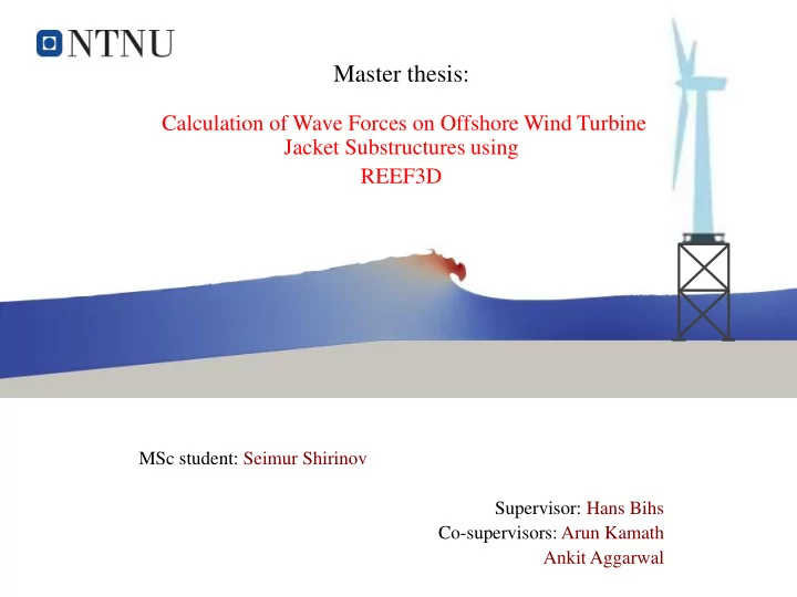

Master thesis: Calculation of Wave Forces on Offshore Wind Turbine Jacket Substructures using REEF3D MSc student: Seimur Shirinov Supervisor: Hans Bihs Co-supervisors: Arun Kamath Ankit Aggarwal
ISSUES 1. Highly varying aerodynamic and hydrodynamic loads 2. Harsh sea environment such as in North sea 3. Considerable costs and time required by laboratory experiments 4. Complex behavior of the forces acting on the structure under breaking waves 5. Breaking waves exerting very high impact forces in very short duration 6. The performance and fatigue life of the offshore wind turbine is strongly affected Fig. 1. Dong et al. (2012)
REEF3D open-source software • Reynolds Averaged Navier-Stokes equations + Continuity equation • Turbulence modeling • Wave theories applications • Numerical Wave Tank setup Fig. 2. Wave interacting with a Jacket Structure, Hans Bihs, 2018, reef3d.com
Thesis focus on: 1. Breaking wave loads on the jacket 2. local forces on the members of the jacket structure 3. Analysis with different wave parameters and different orientations of the jacket 4. Validation of numerical results Fig. 3. Wei et al. (2017)
Large Wave Flume (GWK) of the Coastal Research Centre (FZK) in Hannover, Germany. Fig. 5. Comparison of numerical results for total dynamic forces on Cylinder pile with experimental data. Fig. 4. Mo et al. (2007)
Wave slamming forces on truss structures in shallow water, GWK, Hannover, Germany Fig. 6.1, 6.2 Arntsen et al. (2013) G1 G3 G5 G6 G4 G2 Fig. 6.3. Arntsen et al. (2013)
2D Model (1/2) for Non-breaking wave Free-surface elevation at Gauge 2 Free-surface elevation at Gauge 1 Fig. 7. Comparison of the free surface elevations of numerical results with experimental data at different gauge locations. G2 G1
3D Model (2/2) for Non-breaking wave Fig. 8. Comparison of the free surface elevations for 2D and 3D at Gauge 2 Fig. 9. Comparison of the total dynamic forces on the the structure.
2D Model (1/2) for Breaking wave FSF and Velocity profiles at Gauge 1 Fig. 10. Comparison of the free surface elevation (a) and horizontal particle velocities (b) of numerical results with experimental at Gauge 1 location Gauge 1
Recommend
More recommend