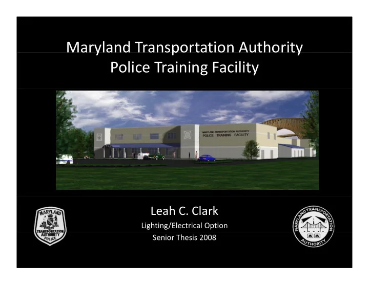

Maryland Transportation Authority y p y Police Training Facility Leah C. Clark Lighting/Electrical Option Senior Thesis 2008
Overview Location: Hawkins Point, Baltimore, Maryland Location: Hawkins Point, Baltimore, Maryland Size: • 42,100 square feet • 2 stories above grade Project Team: • Owner: Maryland Transportation Authority • M echanical and Electrical: Johnson, Mirmiran, & Thompson • Architectural: Rubeling & Associates • Civil and Structural: Carroll Engineering Inc • Civil and Structural: Carroll Engineering, Inc. Cost: $ 15.2 Million
Floor Plan Front Façade Physical Training Gym Physical Training Gym Classroom Firing Range Area g g
Classroom Lighting
Classroom Design Criteria Light Distribution of Task Plane Light Distribution of Task Plane Uniformity on task plane Peripheral Emphasis Control and Flexibility 1) Examination Scene 2) Audio/Visual Presentation Scene / 3) Lecturing Scene Illuminance Levels (to perform task) Illuminance Levels (to perform task)
Classroom Examination Scene A) Linear semi ‐ indirect – 100% B) Cabinet lighting – 100% C) C) Square downlights – 100% S d li h 00%
Classroom Audio/Visual Presentation Scene A) Linear semi ‐ indirect – 50% B) ) Cabinet lighting – 0% g g C) Square downlights – 0%
Classroom Lecturing Scene A) Linear semi ‐ indirect – 25% B) Cabinet lighting – 0% C) Square downlights – 100%
Firing Range Lighting
Firing Range Design Criteria Control and Flexibility •Pseudo-realistic training environments 1) Night-time Condition 2) Typical Interior Condition 3) Glare Condition Light Distribution on Task Plane Distribution will vary based on the real-life situation being simulated situation being simulated Illuminance Levels Night-time Condition – less than 5 fc Typical Interior Condition – avg 30 fc Gl Glare Condition – avg 30 fc + glare C diti 30 f l
Night-time Condition Firing Range
Typical Interior Condition Firing Range
Firing Range Glare Condition
Range Ventilation
Range Ventilation Range Ventilation Guidelines •Optimum ventilation rate is 75 fpm at the firing line with a minimum of 50 fpm should be maintained at the firing line. f •Air should be distributed at least 15 feet behind the shooter with the supply air inlets place on the back wall. air inlets place on the back wall. •High Efficiency Particulate (HEPA) filters should be used to filter all air being exhausted from the firing range. •The range should have a dedicated ventilation system so as not to contaminate other spaces in the building. •Supply and return air systems should be electrically interlocked so that one can not be in use without the other. •High efficiency heating and cooling coils lower the interference with air flow •High efficiency heating and cooling coils lower the interference with air flow balance.
Range Ventilation Existing System
Range Ventilation Proposed Solution
Range Ventilation Sizing of the Proposed System Q = vA = (75 ft/min)*(100ft)*(11ft) = 82 500 ft 3 /min Q = vA = (75 ft/min) (100ft) (11ft) = 82,500 ft /min 2 AHUs supplying 42,000 cfm Affinity laws were applied to determine the motor size to power the AHUs 125 hp motor
Electrical Resizing for Mechanical
Electrical Resizing for Mechanical Resizing for Mechanical Breadth MCA = FLC * 125% = 156A * 1.25 = 195A Branch Circuits (4) 3/0 AWG and (1) #3 AWG ground in 2” conduit (4) 3/0 AWG and (1) #3 AWG ground in 2 conduit MOPD = 156A * 250% = 156A * 2.50 = 390A (max) MOPD 156A 250% 156A 2.50 390A (max) Circuits 7 and 8 serving AHU-1 and AHU-2 350A 3-pole circuit breakers Panelboard MDP 5 sets of (4) 400 MCM and (1) 4/0 AWG ground in 3” conduit 5 sets of (4) 400 MCM and (1) 4/0 AWG ground in 3 conduit
Acoustical Considerations
Acoustical Considerations Classroom Firing Range
Acoustical Considerations Noise Criterion (NC) for classrooms greater than 750 ft 2 Less than NC-35 Basic Method used to calculate Noise Reduction (NR) NR = TL + 10 log (A rec /S common wall ) Source Sound Pressure Levels for Firearms
•A more conventional noise reducing wall assembly consisting of painted hollow (8") CMU and 5/8 ” gypsum board on resilient channels wit Acoustical Considerations Conventional Wall Assembly
Acoustical Considerations Conventional Wall Assembly NR = TL + 10 log (A rec /S common wall )
Acoustical Considerations Conventional Wall Assembly
Acoustical Considerations Proposed Wall Assembly
Acoustical Considerations Conventional Wall Assembly NR = TL + 10 log (A rec /S common wall )
Acoustical Considerations Conventional Wall Assembly
Firing Range Conclusions Classroom
Conclusions Range Ventilation g Acoustical Considerations
Acknowledgements Thanks! Maryland Transportation Authority Johnson, Mirmiran, & Thompson Matt Keller Matt Keller Jim Good Dr. Mistrick Ted Dannerth AE Faculty and Staff AE Classmates Family & Friends
Questions? Leah C. Clark Lighting/Electrical Option Senior Thesis 2008
Recommend
More recommend