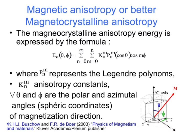

Magnetic anisotropy or better Magnetocrystalline anisotropy • The magneocrystalline anisotropy energy is expressed by the formula : n mPn m cos Ea , cos m Kn n 0 m 0 m • where represents the Legendre polynoms, Pn m • anisotropy constants, Kn M and are the polar and azimutal C axis angles (sphéric coordinates) of magnetization direction. •K.H.J. Buschow and F.R. de Boer (2003) “Physics of Magnetism and materials” Kluver Academic/Plenum publisher
Magnetic anisotropy or better Magnetocrystalline anisotropy uniaxial symmetry 2 4 E a , K sin K sin 1 2 M C axis C axis M Hexagonal symmetry 2 4 6 4 E a , K sin K sin K sin K sin cos( 6 ) ... 1 2 3 4 a E is an important parameter for soft and hard magnetic materials
Crystal electric field l m rlYl m(r) V(r) Al m l l m Al Crystal electric field coefficients m Yl Spherical harmonics • Coupling with the 4f electronic shell • Favors the orientation of the shell in the electric field gradient
• Hutchings, M. T. (1964) Solid state phys., 16, 227. • Stevens coefficients
Anisotropy constant may vary with T ! May even change of sign
How to identify the Easy Magnetization Direction X-ray diffraction Magnetization curves ( 0 0 2 ) 1200 ( 0 0 1 ) 1000 1.2 field-oriented M 10 6 A/m Intensity (a.u.) 800 ( 1 1 1 ) ( 1 0 1 ) 0.8 600 Si Si ( 2 0 0 ) free powder ( 1 1 0 ) 400 ( 2 0 1 ) Si ( 1 1 2 ) ( 2 1 1 ) 0.4 200 0 40 30 40 50 60 70 80 2 (°) 80 0 Neutron diffraction experiments H 0 10 4 A/m
Anisotropy field H a = 2 K 1 / µ 0 M s H a = 2 K 1 / µ 0 M s +… Magnetization ( B / u.f.) C axis M Nd 2 Fe 13 GaBH 3.7 (300 K) M //c M c c a See talk O. Fruchart H < H Higher order : Applied field (kOe)
Rare earth contribution to magnetocrystalline anisotropy 2 J r 2 4f 3 0 K 1 T 0 (3J z J(J 1))A 2 Purely Atomic parameter J second order Stevens coefficient ( J ) for R 3+ ( 3 J z J ( J 1 )) r 2 4f 4f shell Atomic environment J < 0 J > 0 electric charges 0 A 2 Crystal electric field gradient J r 2 4f (3J z J(J 1)) Remark : Quadrupolar moment
nd 2 order Stevens coefficient Ion Ce 3+ Pr 3+ Nd 3+ Sm 3+ Tb 3+ Dy 3+ Ho 3+ Er 3+ Tm 3+ Yb 3+ J 10 2 -5,71 -2,10 -0,64 +4,13 -1,01 -0,63 -0,22 +0,25 +1,01 +3,17 Similar equation for K 2 ; K 3 and so on J < 0 • References J > 0 • K.N.R. Taylor et M.I. Darby, Physics of Rare Earth Solids, edited by Chapmam and Hall Ltd, London, 1972, p. 22. ISBN 0 412 101602. • K.W.H. Stevens, Proc. Phys. Soc., 65, (1951), p. 209. • K.H.J. Buschow and F.R. de Boer (2003) “Physics of Magnetism and materials” Kluver Academic/Plenum publisher • K.H.J. Buschow, Magnetism and Processing of Permanent Magnet Materials, Handbook of Magnetic Materials Volume 10, édited by K.H.J. Buschow, Elsevier Science B.V., Amsterdam (1997), Ch. 4, p. 463. ISBN 0 444 853138 .
100 More complex behaviour : PrCo 4 Ga 80 (EMD- c axis) (°) ( 0 0 2 ) 1200 60 ( 0 0 1 ) 1000 40 T SR = 160 K field-oriented Intensity (a.u.) 800 20 ( 1 1 1 ) ( 1 0 1 ) 0 600 Si 0 50 100 150 200 250 300 Si ( 2 0 0 ) free powder ( 1 1 0 ) T(K) 400 ( 2 0 1 ) Si ( 1 1 2 ) ( 2 1 1 ) 4 K 168 K 250 K 200 6 30 40 50 60 70 80 4 2 (°) M z (µ B /f.u.) 2 c-axis canted PrCo 4 Ga 3 (a, b) plane 0 6 PrCo 5 2 4 K 168 K 250 K 4 YCo 4 Ga 1 M x (µ B /f.u.) 2 YCo 5 0 0 -2 0 200 400 600 800 1000 T (K) -4 0 90 180 270 360 (°)
Complex behaviour YFe 11 Ti LuFe 11 Ti Axial Conical TmFe 11 Ti Planar ErFe 11 Ti HoFe 11 Ti Magnetic phase diagram DyFe 11 Ti TbFe 11 Ti GdFe 11 Ti SmFe 11 Ti NdFe 11 Ti PrFe 11 Ti CeFe 11 Ti 0 100 200 300 400 500 600 700 Temperature ( K )
Recommend
More recommend