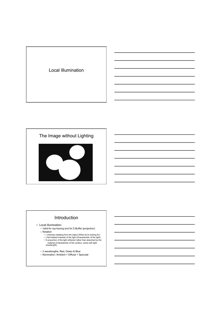

Local Illumination The Image without Lighting Introduction • Local illumination – Valid for ray-tracing and for Z-Buffer (projection) – Notation • I r Intensity radiating from the object (What we’re looking for) • I i Normalized intensity of the light (Characteristic of the light) • K proportion of the light reflected rather than absorbed by the material (Characteristic of the surface; varies with light wavelength) – 3 wavelengths: Red, Green & Blue – Illumination: Ambient + Diffuse + Specular
Ambient Light • Approximation to global illumination – Each object is illuminated to a certain extent by “stray” light – Constant across a whole object • Often used simply to make sure everything is lit, just in case it isn’t struck by light direct from a light source Ambient Light • Ambient light usually set for whole scene (I a ) • Each object reflects only a proportion of that (k a ) • So far then I r = k a I a Lighting Equation #1 But we use RGB so I r, red = k a,red I a,red I r,green = k a,green I a,green I r,blue = k a,blue I a,blue
The Image - Ambient Lambert’s Law • Diffuse reflector scatters light • Assume equality in all directions • Called Lambertian surface • Angle of incoming light is still critical Lambert’s Law d’ d L is the direction to the light N is the surface normal • Incoming intensity of light is proportional to d • d is proportional to cos Θ = N.L Reflected intensity is proportional to cos Θ
Diffuse Light • The normalised intensity of the light incident on the surface due to a ray from a light source • The light reflected due to Lambert’s law • The proportion of light reflected rather than absorbed (k d ) Lighting Equation #2 I r = k a I a + k d I i (n.l) • Ambient and diffuse components • Again k d is wavelength dependent and we work with k d,red k d,green and k d, blue Multiple Lights? • Add the diffuse terms m I r = k a I a + Σ k d I i,j (n.l j ) j =1 • I i,j is the incoming intensity of light j • l j is the vector to light j
The Image - Diffuse Perfect Specularity θ θ • Would almost never see the specular highlight Imperfect Specularity (Phong) • E is the direction to the eye N • N is the normal H E T h • L is the direction to the light e i L m a The • H bisects E and L surface
Specular Component k s I i (h.n) m • m is the power of the light (shininess) – High m implies smaller specular highlight – Low m makes the highlight more blurred Lighting Equation #3 I r = k a I a + I i (k d (n.l) + k s (h.n) m ) • Ambient, diffuse & specular components • Again if there are multiple lights there is a sum of the specular and diffuse components for each light ( This is the time to worry about clamping values to 0,1 required for monitor display) The Image - Specular Small and big specular highlight
Conclusions • We can now colour the pixels by combining – Ambient light – Diffuse reflections – Specular reflections Summed over several light sources • We need – Shadows – Better model for light reflection of the object: BRDF – Global illumination
Recommend
More recommend