
SLIDE 1
Inf2C Computer Systems - 2010-2011 1
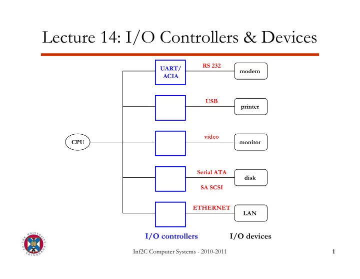
Lecture 14: I/O Controllers & Devices
I/O controllers
CPU UART/ ACIA modem printer monitor disk RS 232 USB video Serial ATA SA SCSI
I/O devices
LAN ETHERNET
Lecture 14: I/O Controllers & Devices RS 232 UART/ modem ACIA - - PowerPoint PPT Presentation
Lecture 14: I/O Controllers & Devices RS 232 UART/ modem ACIA USB printer video CPU monitor Serial ATA disk SA SCSI ETHERNET LAN I/O controllers I/O devices Inf2C Computer Systems - 2010-2011 1 Computer System Organization
Inf2C Computer Systems - 2010-2011 1
I/O controllers
CPU UART/ ACIA modem printer monitor disk RS 232 USB video Serial ATA SA SCSI
I/O devices
LAN ETHERNET
Inf2C Computer Systems - 2010-2011 2
Memory bus
CPU
Cache Main memory Bus adapter I/O bus I/O controller I/O controller I/O controller
Inf2C Computer Systems - 2010-2011 3
– 2 signal wires (one for each direction) + ground reference
Tx data wire (CPU to I/O device) Rx data wire (I/O device to CPU) GROUND wire
Inf2C Computer Systems - 2010-2011 4
– 1 character = 10 or 11 bits (including signaling) – Idle state is represented by a constant “1”
– odd → total number of “1”s (including parity bit) is odd – even → total number of “1”s is even
1 idle (1) start bit (0) data (7 or 8 bits) parity bit stop bit (1)
Inf2C Computer Systems - 2010-2011 5
shift register shift register serial data in receiver status Rx data register Tx data register transmitter status serial data out write control data data read control RECEIVER TRANSMITTER FROM/TO I/O device FROM/TO processor
1 8 8 1 1 1 8 8
Inf2C Computer Systems - 2010-2011 6
– data lines (8 bits) – control lines (READ and WRITE signals), – address lines (some few bits) → each I/O controller is assigned a range of addresses for its registers
Inf2C Computer Systems - 2010-2011 7
– I/O controller registers (data and control) are mapped to a dedicated portion of memory and are accessed with regular load and store instructions – Takes bus bandwidth away from CPU-memory
– More flexible – Off-load memory bus (multiple I/O devices appear as a single device to the memory bus) – Used in high-performance systems
Inf2C Computer Systems - 2010-2011 8
Tx data register Rx data register status register WRITE
8
READ
8
READ
8
UART data 128 bits address 32 bits memory bus from processor
receiver status bit receiver status bit
data 8 bits address 8 bits read/ write control 2 bits I/O bus from
Inf2C Computer Systems - 2010-2011 9
User process calls OS at regular intervals to check status of I/O
Time-consuming Not flexible Used in embedded systems
I/O controller interrupts user process to signal an I/O event Used in general purpose systems
Inf2C Computer Systems - 2010-2011 10
– 5400-15000 rpm
arm + head platter axis track sector arm + head
Inf2C Computer Systems - 2010-2011 11
– Seek time: time to move head to appropriate track (< 10ms for hard disk; < 100ms for floppy) – Rotational latency: time to wait for appropriate sector to arrive underneath the head (< 10ms for hard disk)
Spinning speed
– Spinning speed and recording density – 75-125 MB/s for hard disk
Inf2C Computer Systems - 2010-2011 12
– EIDE: simple, bus structure is similar to I/O or memory bus – SCSI: flexible, requires special bus controller to connect to I/O or memory bus
– Exchange data and control between CPU and controller – Command register → tells controller what to do next e.g. Seek n Read Sector m Write Sector m Format Track
High-level commands
Inf2C Computer Systems - 2010-2011 13
Inf2C Computer Systems - 2010-2011 14
Inf2C Computer Systems - 2010-2011 15
– Address register → position in memory of next data to be read/written – Data register → temporary storage for data to be transferred – Length register → number of bytes remaining to be transferred
Inf2C Computer Systems - 2010-2011 16
address
Address register
data
DMA Controller disk Data register Length register CPU Memory
control Bus Request Bus Grant
FROM/ TO
Inf2C Computer Systems - 2010-2011 17
Inf2C Computer Systems - 2010-2011 18
– Authorizes CPU or DMA controller to access memory at any given time
– Bus Request → asserted by DMA when it requires the bus – Bus Grant → asserted by the CPU when it is not using the bus and thus DMA can use it – In case of conflicting requests in the same cycle, CPU usually has priority
hundred nanometers and a thickness of about ten, it flies above the platter at a speed of up to 15,000 RPM, at a height that’s the equivalent
you begin to get an idea of their significance.
and the hard-disk platter were the surface of the Earth:- – The head would fly at Mach 800 – At less than one centimeter from the ground – And count every blade of grass – Making fewer than 10 unrecoverable counting errors in an area equivalent to all of Ireland.
– (source: Matthieu Lamelot, Tom’s Hardware)
Inf2C Computer Systems - 2010-2011 19