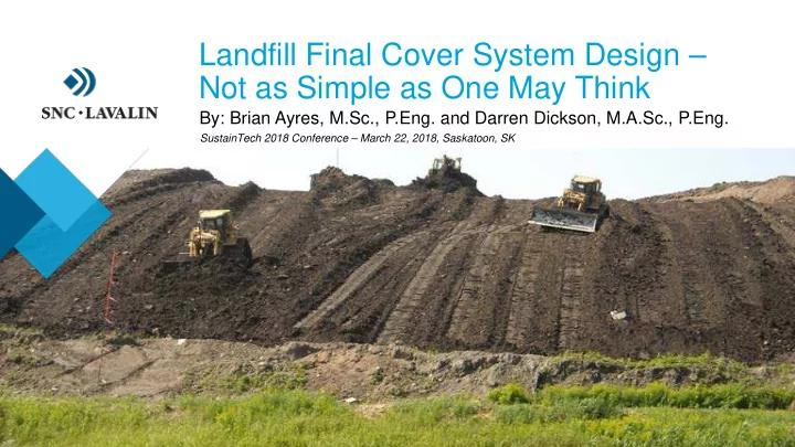
› Landfill Final Cover System Design – Not as Simple as One May Think › By: Brian Ayres, M.Sc., P.Eng. and Darren Dickson, M.A.Sc., P.Eng. SustainTech 2018 Conference – March 22, 2018, Saskatoon, SK
A world leader Founded in 1911, SNC-Lavalin is one of the leading engineering and construction groups in the world and a major player in the ownership of infrastructure. From offices in over 50 countries, SNC-Lavalin's employees are proud to build what matters. Our teams provide EPC and EPCM services to clients in a variety of industry sectors, including oil and gas, mining and metallurgy, infrastructure and power. SNC-Lavalin can also combine these services with its financing and operations and maintenance capabilities to provide complete end-to-end project solutions. 2
Presentation Outline › Typical Municipal Solid Waste (MSW) Landfill Facilities and Characteristics › Purpose and Design Functions of Landfill Final Cover Systems (LFCSs) › Key Factors Influencing Design and Performance of LFCSs › Review of LFCS Design Alternatives › Learnings from Research on Mine Waste Storage Facility (MWSF) Cover Systems › Landfill Closure in Saskatchewan › Key Take-Away Messages 3
Typical MSW Landfill Facilities in Saskatchewan Typical Environmental Facility Type Typical Characteristics Control Systems Dump or • Established prior to 1990s, • Minimal to none … rely on Legacy Site typically remote or rural areas large buffer zones to Waste • Small waste quantities and manage exposure risks to Varied native soils serviced population receptors Potable water aquifer • Minimal siting considerations Natural • Older and newer facilities • Natural attenuation Waste Attenuation • Small-medium waste quantities processes to reduce and serviced population contaminant concentrations Thick layer of native silts & clays • Relatively thick natural to acceptable levels attenuation zone • Surface water mgmt. (?) Potable water aquifer Engineered • Newer facilities • Leachate collection and Landfill • Larger waste quantities and management serviced population • Surface water mgmt. • An absolute must when hydro- • Landfill gas collection (?) geological setting is poorer • Groundwater intercept. (?) 4
Typical Characteristics of Landfilled MSW › Mostly household refuse, but depends on age of the landfill › Large quantities of construction & demolition (C&D) waste at some sites › High ash and cinder content at many legacy sites from open burning › As organic matter decomposes, landfill gases are produced, comprised mostly of methane and carbon dioxide › As rain and snowmelt water percolate through waste, landfill leachate is generated … a water-based solution containing a variety of pollutants 5
Typical Characteristics of MSW Landfill Leachate Leachate Pollutant Typical Components › Heavy metal concentrations in leachate Groups typically below most drinking water stds. Dissolved organic Acids, alcohols expressed matter as COD or TOC › Substances of potential concern (SOPCs) Inorganic matters Ca, Mg, Na, K, NH 4 , Fe, in most cases are ammonia and salinity, Mn, Cl, SO 4 , HCO and where open burning has occurred, Heavy metals Cd, Cr, Cu, Pb, Ni, Zn PAHs, dioxins and furans Xenobiotic organic Aromatic hydrocarbons, › Chloride a good indicator of leachate compounds (XOCs) phenols, chlorinated aliphatic hydrocarbons, plume leading edge, while boron is a good pesticides & plasticizers measure of mature portion of plume Combustion Dioxins, furans products (Reference: Kjeldsen et al. (2002) – Present and Long-term Composition of MSW Landfill Leachate: A Review) 6
Purpose and Design Functions of Landfill Final Cover Systems (LFCSs) Purpose: › Limit exposure and/or potential risks to human health and the environment post-closure › Facilitate meeting aesthetic and end land-use objectives Typical Design Functions: › Limit potential for direct contact with contaminants › Limit water infiltration to reduce volume of leachate › Control landfill gas emissions so they can be minimized, or concentrated for collection and destruction or use › Provide a growth medium for native plant species 7
Key Factors Influencing Design of a LFCS › End land-use › Substances of potential concern in waste › Receptors and exposure pathways › Extent / efficacy of leachate collection system › Extent / efficacy of landfill gas–to–energy conversion system › Potential for future differential settlement (i.e. density / thickness of waste and stage of organic waste decomposition) › Physical / hydraulic characteristics of on-site or nearby soils in sufficient quantities (Source: https://foresternetwork.com/daily/waste/waste- collection/revisiting-the-cover-on-final-cover-2/) 8
LFCS Requirements from Various Jurisdictions Saskatchewan Alberta Manitoba British Columbia (1998 Draft Guidelines) (2010 Landfill Stds.) (2016 Landfill Stds.) (2016 Landfill Criteria) Organic Layer 0.2 m Subsoil Layer 0.35 m (0.8 m for cultivated land) 0.15 m Organic Layer 0.15 m Organic Layer Barrier Layer Barrier Layer Barrier Layer Clay Soil 0.6 m (K sat ≤10 -5 cm/s 0.5 m 0.5 m 0.6 m (K sat ≤10 -5 cm/s) (K sat ≤10 -7 cm/s) for semi-arid regions) Ontario North Dakota Montana Minnesota (2012 Landfill Stds.) (2009 – Guideline 10) (2017 – ARM 17.50.1403) (2017 – Rule 7035.2815) Organic Layer 0.15 m Organic Layer 0.15 m Subsoil Layer 0.4 m 0.15 m Organic Layer Organic Layer 0.15 m Subsoil Layer 0.15 m Subsoil Layer Barrier Layer Compacted Barrier Layer 0.6 m (soil type/compaction 0.9 m 0.45 m 0.6 m (K sat ≤10 -5 cm/s) (K sat ≤2x10 -6 cm/s) Clay Soil depends on NP max ) 9
Most Common Types of LFCS Designs “Geosynthetic Barrier “Compacted Soil Barrier Cover System” Cover System” “Evapotranspiration (ET) Cover System” 0.15 m Design of this 0.15 m layer often overlooked!! [geocomposite 0.3 to 0.15 m drainage net 0.3 to 0.9 m (GDN) or 0.9 m sand/gravel] 0.6 to 0.10 m Barrier Layer 1.0 m 0.3 to [geosynthetic clay 0.10 m liner (GCL) or 0.6 m 40- to 60-mil linear low-density PE (LLDPE) geomembrane] 10
Research on Mine Waste Storage Facility (MWSF) Cover Systems › MEND (2004) – 5 volume set focused on design, construction, and performance monitoring of MWSF covers › MEND (2007) – focused on design and performance monitoring of MWSF covers from a landform perspective › MEND (2012) – focused on design and construction of MWSF covers situated in a cold region › INAP (2017) – most recent MWSF cover technical guidance document with a global focus 11
Key Lessons Learned from MWSF Case Studies 1) Transfer the methodology, not the design, from site to site … account for site-specific waste, soil, climatic and vegetation conditions Site B Site A 2) Cover system performance should be linked to predicted impacts on receiving environment 3) Greatest physical risk to reclaimed landforms is (from www.geo-slope.com) gully erosion and re-established surface water (Source: www.dailymail.co.uk) drainage courses (McKenna & Dawson, 1997) Equity Silver Mine (BC) WRSF Final Cover Case Study (INAP, 2003): 4) Thickness of root zone / barrier layer Growth Medium protection layer – needs to be thicker to 0.3 m Growth Medium (non-compacted till) 0.4 m provide adequate water for plant growth, Evolution after Barrier Layer Barrier Layer and protect the barrier layer from various 0.5 m 10 years (compacted till) 0.4 m ( thinner due to physical, chemical and biological processes wet/dry cycling ) 12
So how do we Maximize the Potential for Sustained Performance of a LFCS? Physical Integrity: › High degree of compaction of underlying fill materials › Proper management of surface water (runoff and runon) Lower Infiltration / Leachate Rates: › Promote runoff of snowmelt and storm waters › Increase ET w/ diverse, sustained vegetation cover › Adequately protect a barrier layer from degradation Lower Landfill Gas Emissions: › Maintain physical integrity of cover system › Thicker final cover or include a barrier layer 13
Work to Support Landfill Closure in SK › Environmental Site Assessment (ESA): Receptor Source › Typically a limited Phase II ESA investigation to characterize physical site conditions and identify RISK existing and potential future environmental impacts › Involves monitoring well installation, water analyses and comparison to relevant standards, and identification of Pathway SOPCs, receptors, and exposure pathways › Corrective Action Plan (CAP): This forms the basis of a › “a CAP details the methods used to prevent, minimize, Landfill Closure Plan, mitigate, remedy or reclaim adverse effects” (SK MOE, 2015) which, for most sites, › Includes plans for site remediation, final cover profile and will be “monitored grading, and post-closure care and monitoring natural attenuation” 14
Let’s Consider the Water Balance for a Site near Saskatoon (mean annual basis; units of mm) Net Percolation ( NP ) = Water Input ( WI ) – Runoff ( R ) – Evapotranspiration ( ET ) 345-355 WI = rain (277) + snow (91) – 345-355 65-85 250-290 snowpack losses 50-70 260-290 (15-25% of snow) Max. ET ≅ 50-60% of Potential or Lake Evaporation (720) These WB fluxes similar to those measured at the St. Denis study site, 40 km 5 to 15 east of Saskatoon – net 10 to 30 recharge of 1-3 mm/year (1-4% of WI) (3-9% of WI) (Hayashi et al., 1998) 15
Recommend
More recommend
Unleash a World of Digital Possibilities—Browse, Share, and Explore Content Without Boundaries