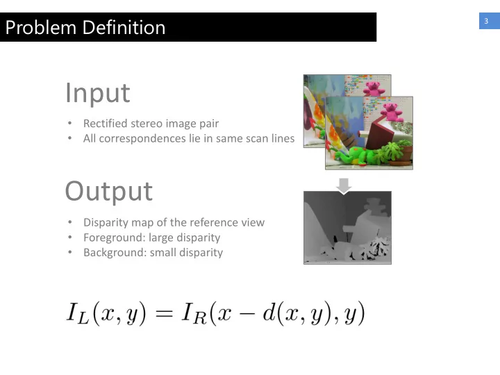

Problem Definition 3 Input • Rectified stereo image pair • All correspondences lie in same scan lines Output • Disparity map of the reference view • Foreground: large disparity • Background: small disparity
Matching Cost Volume 2 𝐷 𝑦, 𝑧, 𝑒 denotes the matching cost of pixel (x,y) at different disparity level d
WTA (Winner Takes All) 3 • 𝐷 𝑦, 𝑧, 𝑒 denotes the matching cost of pixel (x,y) at different disparity level d • Select d with lowest cost as final disparity
Some Milestone Approaches 4 • Graph Cut (Energy Minimization via Graph Cuts) Boykov et al., ICCV 1999 • ASW (Cost Aggregation by adaptive support weight) Yoon and Kweon, CVPR 2005 • SGM (Semi-Global Matching) Hirschmuller, CVPR 2005, PAMI 2008 • PatchMatch Stereo (Cost aggregation using slanted support windows) Bleyer et al., BMVC 2011
Graph Cut 5 • Frame the problem as an energy minimization on a multi- labeled MRF • Solve the MRF by Graph Cut Unary Cost • Photo consistency of each label Pairwise Cost • Penalize disparity difference between neighboring pixels
Graph Cut 6 • Frame the problem as an energy minimization on a multi- labeled MRF • Solve the MRF by Graph Cut
Traditional Local Methods 7 𝐷 𝑦, 𝑧, 𝑒 Cost aggregation Bilateral filter each 𝐷(𝑦, 𝑧, 𝑗) 𝐷 𝐵 𝑦, 𝑧, 𝑒
ASW (Adaptive Support Weights) 8 • Given an initial matching cost volume, • Refine the volume by aggregating cost locally and adaptively
ASW (Adaptive Support Weights) 9 • Given an initial matching cost volume, • Refine the volume by aggregating cost locally and adaptively
SGM (Semi-Global Matching) 10 • Instead of aggregating cost at a local window, • SGM Aggregate cost in paths
SGM (Semi-Global Matching) 11 • Instead of aggregating cost at a local window, • SGM Aggregate cost in paths
PatchMatch Stereo 12 • Parametrize each pixel as a disparity plane • Aggregate cost in the slanted window induced by the plane • Too many (infinite) possible states, solve by PatchMatch
PatchMatch Stereo 13 • Parametrize each pixel as a disparity plane • Aggregate cost in the slanted window induced by the plane • Too many (infinite) possible states, solve by PatchMatch
MeshStereo: A Global Stereo Model with Mesh Alignment Regularization for View Interpolation Chi Zhang, Zhiwei Li, Yanhua Cheng, Rui Cai, Hongyang Chao, Yong Rui Presented by Chi Zhang Dec. 15 th , 2015
Motivation 2 Goal • Output high-quality mesh for view interpolation Motivation • Depth estimation and mesh generation are separated in traditional approach, which is not optimal in terms of rendering • We aim at unifying such separation, and develop an integrated stereo approach for view interpolation
Movitation 3 Traditional Pipeline • I L , I R -> Point Clouds (Disparity Maps) • Point Clouds -> Mesh • Mesh -> New View Angles Ours • I L , I R -> Mesh • Mesh -> New View Angles
Formulation 17 Mesh Representation • Delauney triangulated SLIC Segmentation • Assign a depth value to each vertex • Lifting the 2D triangulation to 3D naturally generate a mesh Technical Difficulty • How to split vertices into multiple copies at depth discontinuities Solution • Assign a splitting probability to each vertex
Formulation 18 Parameterization A Splitting probability for each 2D vertex denoted by α A depth value for each triangle’s barycenter and a normal for each triangle denoted by N , D
Formulation 19 Objective Function • Objective function is a two-layered MRF glued by an Alignment energy term Lower Layer MRF Gluer Upper Layer MRF
Formulation 20 The Lower Layer • The lower layer MRF is on the “dual” grid of the 2D triangulation
Formulation 21 The Lower Layer • Favorites photo-consistent triangles
Formulation 22 The Lower Layer • Encourages normal smoothness. Encouraged Discouraged
Formulation 23 The Upper Layer • The upper layer MRF is on the original grid of the 2D triangulation
Formulation 24 The Upper Layer • Favorite non-split vertices on homogeneous regions
Formulation 25 Similar visual complexity Similar visual complexity Similar visual complexity The Upper Layer • Encourages similar splitting properties when adjacent vertices share similar “visual complexity” Non-similar visual complexity
Formulation 26 The Upper Layer • Encourages similar splitting properties when adjacent vertices share similar “visual complexity”
Formulation 27 The Gluer • Enforce strong alignment or split a 2D vertex to multiple copies in 3D according to corresponding splitting probability
Optimization 28 Objective Function Optimization • Iterative Gradient Descent in the blue part and the orange part • Fix N , D , minimize the orange part w.r.t. α in closed form • Fix α , minimize the blue part by PatchMatch with iterative relaxation ( detail at next page )
Optimization 29 The orange part sub-energy Optimization • Fix α , minimize E LOWER by PatchMatch with iterative relaxation • When 𝜄 goes to ∞ , minimizing E RELAXED is equivalent to minizing E LOWER
Optimization 30 The orange part sub-energy Optimization • Fix α , minimize E LOWER by PatchMatch with iterative relaxation Minimize by PatchMatch Minimize in closed form
Results 31 Stereo Results on Herodion Dataset
Results 32 Ranking on Midd3 benchmark
Results 33 Examples of generated meshes
Results 34 Some synthesized views
Results 35 Some synthesized views
Conclusion 18 • We proposed an integrated stereo model for view interpolation • Take I L , I R as inputs, produce a mesh directly • It achieves state-of-the-arts performance on both stereo quality and rendering
Thank you! The End
Recommend
More recommend