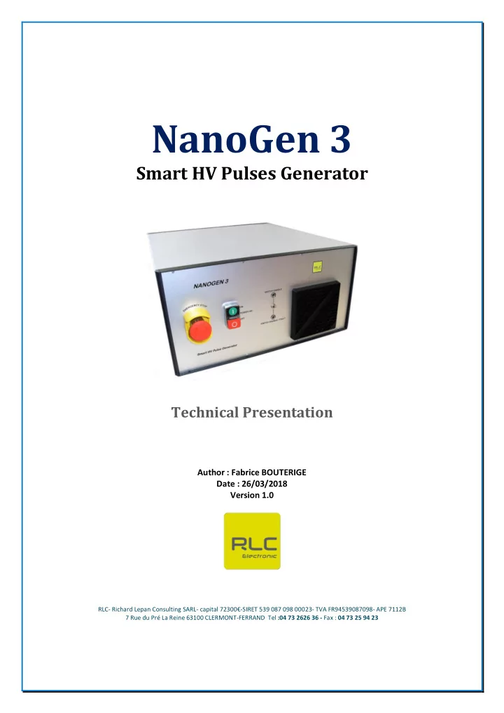

NanoGen 3 Smart HV Pulses Generator Technical Presentation Author : Fabrice BOUTERIGE Date : 26/03/2018 Version 1.0 RLC- Richard Lepan Consulting SARL- capital 72300 € -SIRET 539 087 098 00023- TVA FR94539087098- APE 7112B 7 Rue du Pré La Reine 63100 CLERMONT-FERRAND Tel :04 73 2626 36 - Fax : 04 73 25 94 23
I. Table of Contents 2 I. Table of Contents ............................................................................................................................. 3 II. NanoGen3 Presentation ................................................................................................................... ........................................................................................................................................ 3 II.1. Main Features ....................................................................................................................................... 3 II.2. Internal Wiring II.3. Description of Front Panel ...................................................................................................................... 4 II.4. Description of Rear Panel ...................................................................................................................... 4 II.5. Global Wiring ......................................................................................................................................... 5 6 III. CPU Board ...................................................................................................................................... 7 IV. HV Power Switch Board .................................................................................................................. V. Oscillograms ................................................................................................................................... 8 9 VI. NanoGen 3 HMI .............................................................................................................................. 10 VII. Maximum Power Limitation......................................................................................................... Technical Presentation | RLC, CLERMONT-FERRAND 2 NanoGen3 : Smart HV Pulses Generator (V1.0)
II. NanoGen3 Presentation II.1. Main Features Voltage Adjust 0-30 kV Pulse Frequency 1Hz - 100 kHz Pulse Width 250 ns - 25µs Duty cycle 0.1% - 50% Output Current max 50A at Fmax = 1 kHz, pulse width max = 10µs or duty cycle max = 1 % II.2. Internal Wiring CPU Box 180V AuxSwitch Supply 15V AuxSwitch Switch Driver Supply Technical Presentation | RLC, CLERMONT-FERRAND 3 NanoGen3 : Smart HV Pulses Generator (V1.0)
II.3. Description of Front Panel - Switch « EMERGENCY STOP » - Switch « POWER ON / OFF » and LED « POWER ON » - Switch « SWITCH ENABLE » : this switch enables or disables the HV Pulses Output - Green LED « SWITCH ENABLE » : LED is on if the HV Pulses Output is enabled - Red LED « SWITCH DISABLE / FAULT » : LED is on if the HV switch is disabled or in fault state II.4. Description of Rear Panel - Input Connector « HVPS IN » : HV Supply Input (30kV max) - Output Connector « HV PULSE OUT » : HV Pulse Outputs - GND Connector « GND STAR » :HV Ground - SUBD9 Connector « COMPC RS232 » :RS232 Communication with Optical Fiber adaptator - SUBD15 Connector « COM HVPS ANALOG » :HV Power Supply Analog Control Interface - BNC Connector « GENER INPUT » :Input from External Generator - BNC Connector « SYNCHRO OUTPUT » :Synchronization Output Technical Presentation | RLC, CLERMONT-FERRAND 4 NanoGen3 : Smart HV Pulses Generator (V1.0)
II.5. Global Wiring HV Supply Computer NanoGen 3 RS232 HV Optical fiberlink GND ANALOG PULSES POWER COM OUT RETURN WARNING ! SHIELD POWER RETURN must be connected to GND STAR Faraday Cage Technical Presentation | RLC, CLERMONT-FERRAND 5 NanoGen3 : Smart HV Pulses Generator (V1.0)
III. CPU Board The CPU Board : - manages the RS232 communication with the PC - controls the external HV Power supply - generates the PWM or BURST signal to control the HV Power Switch FRONT PANEL PC RS232 Front Panel RS232 Driver Control HV Power Supply INTERFACE Control Voltage Adaptation Analog Programming Voltage Interface Isolation Enable HV Supply Control Unit Numeric Output Enable Control Isolation Processor Monitor Voltage Adaptation Analog Microcontroller Voltage Monitoring Interface Isolation 5V Pulses Output Signal 220V Rear Panel Rear Panel Power Supply HVPS EXT Control Synchro Generation Management Management EXT GENERATOR SYNCHRO HVPS INTERFACE Technical Presentation | RLC, CLERMONT-FERRAND 6 NanoGen3 : Smart HV Pulses Generator (V1.0)
IV. HV Power Switch Board The HV Power Swicth Board is based on the BELHKE fast high voltage transistor switch HTS 301-10-GSM. SWITCH ENABLE + HV Suplly Input SWITCH DISABLE / FAULT Current Front Panel Limiter Interface Switch High-Speed HV PULSES 5V Pulses Driver HV Switch OUT Input Signal Power Current Management Limiter HV Swicth Supply 15 VDC and 180VDC Technical Presentation | RLC, CLERMONT-FERRAND 7 NanoGen3 : Smart HV Pulses Generator (V1.0)
V. Oscillograms HV Output Pulses Technical Presentation | RLC, CLERMONT-FERRAND 8 NanoGen3 : Smart HV Pulses Generator (V1.0)
VI. NanoGen 3 HMI The NanoGen3 is controlled by a « Human-Machine Interface », developed by RLC, that can be installed on any PC or on a laptop. Control the NanoGen3 with the NanoGen 3 HMI Optical fiber forRS232 link The NanoGen 3 HMI controls : - The external HV Power Supply Output Voltage / ON / OFF - The PWM or BURST Output Pulses parameters Pulse Frequency / Pulse duration… Technical Presentation | RLC, CLERMONT-FERRAND 9 NanoGen3 : Smart HV Pulses Generator (V1.0)
VII. Maximum Power Limitation The yelow line represents the maximum power limitation. The safety area is under this line. Thanks to the new software, the user can not go beyond the maximum power limits. Technical Presentation | RLC, CLERMONT-FERRAND 10 NanoGen3 : Smart HV Pulses Generator (V1.0)
Recommend
More recommend