
How to Handle Multiple Displays in a T errain File Presented by: Denise Broom CADD Support Specialist
Basic Workflow • Create the DTM file. • Import the T errain from TIN file • Create New Models… • Contours • Triangles • Set Up Models for Display • Reference to Other Files
Create the DTM File • Create File/Project • Under Roadway.CTL and Roadway Design Files (DGN) • Digital T errain Model/ TIN Model – 3D
Import the T errain Other options also available for Creating/Importing… • From ASCII File • By Graphical Filter • From Point Cloud • From Elements
Import the T errain • Default Model contains the original imported data. • Project Explorer (In the Model with imported data) • Civil Model - Can be used to update the data from the source. • Civil Standards - View the T errain Feature Definitions in the Active File.
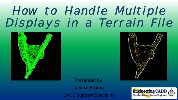
Create New Models • Create New Models… • 2D models that will be used to reference to other design files when the information is needed. • Recommended • Contours • Triangles • Note: In SS4, these will be set up with the file when Create File/Project is used to create the GDTMRD file.
Set Up Models for Display • Reference the Default model to the current model (Contours or Triangles) • Select the boundary element of the T errain and then select Element Information. • T urn On the option you would like to see displayed under Calculated Features Display. • T urn On Override Symbology • This keeps the settings from changing the view/display in the Default model.
Set Up Models for Display • At the top of the Element Information dialog, expand the T errain Element options. • Under Calculated Features Display > Contours, options are available to change the settings for the interval, precision, and level symbology. • T ext Style and Drawing Scale controls the text size.
Reference to Other Files • Select the T errain element and then select Element Information. • T urn ON the Override Symbology option under Reference. • Select the T emplate to change the display setting, if desired. (I.E. contours, triangles, boundary, etc.) • Note: When Referencing Contours or Triangles model, turn on Live Nesting.
Reference to Other Files • If a template does not exist with the desired display option, an Element T emplate can be added to the file.
Questions… Thank you for attending today’s webinar. Need some HELP? Contact me… (850) 414-4751 E-mail: Denise.Broom@dot.state.fl.us OR: ecso.support@dot.state.fl.us http :// www.dot.state.fl.us/ecso FDOT CADD Support Forum On-line http://communities.bentley.com/communities/user_communities/fdot_cadd_su pport/default.aspx
Recommend
More recommend