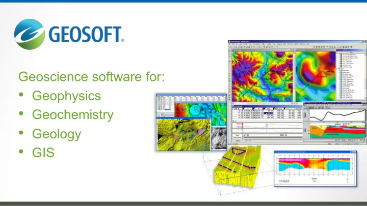

Geoscience software for: • Geophysics • Geochemistry • Geology • GIS
How does Geosoft use EM & Electrical methods? IP & DC resistivity • QC, processing and 3D pseudosection visualizeation • 3D inversion FDEM • Visualization and basic processing • FDEM pseudo 3D inversion TDEM for UXO –EM61 MK2, (3-4 time gates) • Import, processing, target picking, depth estimates 7 forward modelling TDEM for UXO – Geometrics - Metal Mapper • Dynamic surveys for target locating • Processing, target picking, depth estimates, high level classification (21 time gates) • Static surveys for classification • Ordinance classification (122 time gates) 2
Conventional EM Sensors Not usually good for classification EM61 • Coarse measurement of eddy current decay (four time windows or gates) • Point response measured at series of locations must be combined to fully interrogate target • Small sensor location errors (~1 cm) compromise ability to estimate polarizability (some simple case exceptions)
Conventional EM Sensors Horizontal Nose Down
Why Do Classification? Munitions Response Typical Cost Breakout Indirect Cost 50 45 Direct Cost 40 35 30 Cost - $B 25 20 15 10 5 0 Site Survey and Vegetation Scrap Metal UXO Removal & Assessment Mapping Removal Removal Disposal Defense Science Board Task Force on UXO
Advanced EM Sensors Designed for Classification To observe the complete EM response pattern the object must be excited and measured from all directions • multi-axis coil sensors or • single axis coil arrays Multi-axis coil array Single axis planar array
Advanced EM Sensors MetalMapper • 3 multi-axis transmitters • 7 multi-axis receivers MetalMapper 2x2 • 4 coil transmitter array • 4 multi-axis receivers Typical static survey mode, 122 gates over 25ms
Extracting ‘Intrinsic’ Features Plan view of 2x2 sensor Dipole Response Model Inverse Operation Rx 10 1 10 0 Polarizability 10 -1 Transients P 1 from Rx cube P 2 10 -2 P 3 10 -3 voltage 0.1 1 10 Time (ms) time (ms)
Polarizability’s The solution for classification – intrinsic features EM response is decomposed into components along three orthogonal principal axis directions • Principal axis directions correspond to fundamental excitation modes of target • Magnetic polarizabilities are specific responses to unit excitation along each of target’s principal axis Principal axis polarizabilities • Completely describe EM response of target • Intrinsic to the source
Measured Decays Convolve Intrinsic Response with Relative Position and Orientation – Position “A” Tx0 Tx1 R(X) R(Y) R(Z) R(X) R(Y) R(Z) Rx0 Rx0 Rx1 Rx1 Rx2 Rx2 Rx3 Rx3 Tx3 Tx2 R(X) R(Y) R(Z) R(X) R(Y) R(Z) Rx0 Rx0 10 1 10 0 Rx1 Rx1 Polarizability 10 -1 P 1 Rx2 Rx2 P 2 10 -2 P 3 Rx3 Rx3 10 -3 0.1 1 10 Time (ms)
Measured Decays Convolve Intrinsic Response with Relative Position and Orientation – Position “B” Tx0 Tx1 R(X) R(Y) R(Z) R(X) R(Y) R(Z) Rx0 Rx0 Rx1 Rx1 Rx2 Rx2 Rx3 Rx3 Tx3 Tx2 R(X) R(Y) R(Z) R(X) R(Y) R(Z) Rx0 Rx0 10 1 10 0 Rx1 Rx1 Polarizability 10 -1 P 1 Rx2 Rx2 P 2 10 -2 P 3 Rx3 Rx3 10 -3 0.1 1 10 Time (ms)
Measured Decays Convolve Intrinsic Response with Relative Position and Orientation – Position “C” Tx0 Tx1 R(X) R(Y) R(Z) R(X) R(Y) R(Z) Rx0 Rx0 Rx1 Rx1 Rx2 Rx2 Rx3 Rx3 Tx3 Tx2 R(X) R(Y) R(Z) R(X) R(Y) R(Z) Rx0 Rx0 10 1 10 0 Rx1 Rx1 Polarizability 10 -1 P 1 Rx2 Rx2 P 2 10 -2 P 3 Rx3 Rx3 10 -3 0.1 1 10 Time (ms)
Polarizabilities Principal axis polarizabilities completely describe EM response of target § intrinsic to the target § invariant to burial depth or target orientation Polarizability Property Target Property Decay Rate Wall Thickness 37mm projectile Relative Magnitude Shape Total Magnitude Size (volume)
Classification Signature Matching What an unknown target “looks like” in EM sense • Compares polarizability against bank of signatures for expected munitions and other training objects
Classification Signature Variability EM signatures of nominally identical items can differ • Different subtypes, damage, inversion errors due to noise Matching procedures must tolerate some variability e.g. 37mm projectile rotating band effects band at base band missing band in middle
Ranked Source List Classify and Rank Sources • Combine match metric • Size and Decay • Signal amplitude • Source to array distance
Future plans and challenges? • Marine EM • Develop our current tools for EM61 to be marine compatible • Work with Geometrics to develop an advanced EM system for classification • 3D TDEM inversion 17
Please visit Geosoft at Booth G8 or visit www.Geosoft.com 18
Recommend
More recommend