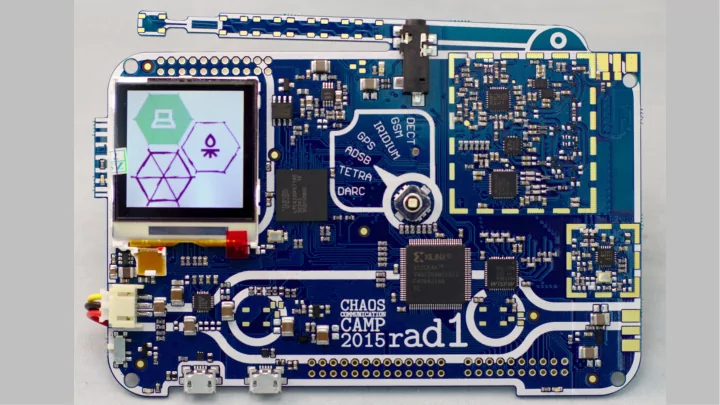

History
Why an SDR? ● Have something useful way after camp ● Don't just put some sensor on it that next phone generation has by default ● Give an SDR to people who would not get one otherwise
Open Hardware: HackRF One ● Developed and produced by Michael Ossmann ● License: GPLv2 (Hard and software) ● Dual Core ARM Cortex M4 + M0 ● 1 MHz – 6 GHz range ● 20 Msps maximum sample rate ● USB 2.0 port
Open Source Firmware Software ● r0ketlib GNURadio ● – Adapted code from previous project – Display, l0dables, fonts Host based signal processing – ● hackrf (firmware) gr-osmosdr ● – SDR support GNURadio source/sink block – – Some initialization – CPLD flashing libhackrf ● ● libopencm3 Basic tools, debug functionality – – Hardware initialization & abstraction dfu-util ● Portapack (archived version) ● – Basic embedded signal processing USB bootloader support – ● FatFS – Portable FAT implementation
Sponsoring: Time and Quantity ● It took a lot of time to get the OK from some sponsors ● We initially communicated a goal of 3000 devices ● Got an estimate of 4500 visitors afterwards – Had to wait again for (much quicker) approval
Sponsoring: Design Changes ● Overall similar RF- Path to HackRF One ● Different mixer with external frequency generator to save cost ● Different RF-Switches ● Different LNAs ● Max 4 GHz design
Sponsoring: Design Changes ● Overall similar RF- Path to HackRF One ● Different mixer with external frequency generator to save cost ● Different RF-Switches ● Different LNAs ● Max 4 GHz design
Timeline
Advice ● Start early, take risks early SHA2016 team is already – meeting ● Lead times of components and the PCB could have killed the project ● Had to resort to ultra fast shipping of prototypes to gain some days
EAGLE vs. KiCad ● HackRF One design is in KiCad Most team members were familiar – with EAGLE ● Made mistakes while copying the schematic... ● The ISP pin is missing a pull-up May cause the rad1o to not boot – Apparently not an issue, but the pin – is very touchy
Nerdkorea at Camp
Prototype 1 ● EAGLE symbol of the CPU had some pins swapped Among them: VCC and GND – ● We had to drill out a via with a 0.4 mm hole to disconnect a ball of the BGA ● All other pins were accessible through the pin headers
“Prototype” 2 ● Make or break – Just for verification ● Ground plane #$%& Prototype 2 PCB Production PCB (DPF Viewer) (gerbv)
Application: rfapp ● scope – Shows an RF waterfall – Selectable frequency – Selectable timescale – Bandwidth: 2 MHz
Application: rfapp ● FM Receiver / Transmitter – Wideband FM – Push to talk – Thanks to @hilse
Application: HackRF App ● Status display for different HackRF mode settings ● Choose HKRF-APP in the bootloader
Application: HackRF App ● Status display for different HackRF mode settings ● Choose HKRF-APP in the bootloader
Application: HackRF App ● Status display for different HackRF mode settings ● Choose HKRF-APP in the bootloader
l0ungel1cht ● Takes DMX data and transmits commands to other rad1os ● Using rflib from @hilse: Moves SDR processing to M0 core
Demo: Remote Controlled Power Socket
Possible Standalone Applications for the rad1o ● No WiFi jammers please :) ● Simple “video” streaming ● RF replay device ● USB filter ● Self made home automation ● USB debugging ● Passive indoor localization ● Very good general SDR introduction: http://greatscottgadgets.com/sdr
● Mailing list: rad1o@lists.muc.ccc.de ● GitHub: https://github.com/rad1o/ ● Wiki: https://rad1o.badge.events.ccc.de ● twitter: @rad1obadge Thanks to all people involved in the project ● https://media.ccc.de/v/camp2015-6884-the_rad1o ● https://media.ccc.de/v/dg56-Hands-on_Rad1o ● https://media.ccc.de/v/32c3-7153-rad1o
Recommend
More recommend