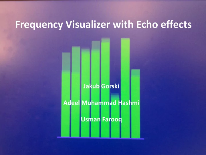

Frequency Visualizer with Echo effects Jakub Gorski Adeel Muhammad Hashmi Usman Farooq
Block Diagram
Initially Proposed Architecture
Modified Architecture
Hardware Components used in the Hardware; • Nexys-3, Spartan 6 FPGA Kit • PmodAD2 • PmodAMP1 • Circuitry for 3.5mm microphone Jack • Low pass filter
Hardware…FIR Filter Design • Filter block is connected to data register via mb_plb buss interface. • Total of 8, 32-tap time-multiplexed Band-pass FIR filter are implemented. • The Direct form FIR filters cannot be implemented since the total number of Multipliers required for the design will be 8 x 32 = 256, which is not Implementation of a Time multiplexed FIR Filter feasible on the board.
Low end Mid base Low Midrange High Lower Middle Top end midrange midrange highs highs 10-100Hz 100- 300- 600- 1.2kHz- 2.4kHz- 4.8kHz- 9.6kHz- 300Hz 600Hz 1.2kHz 2.4kHz 4.8kHz 9.6kHz 20kHz Frequency ranges of 8 Bands for frequency visualization
Software • Echo Generation • The available Block RAM in Nexys-3 board is 576Kb. • We use an u8 buffer[1100]; • -O3 optimization. • Can enable or disable echo.
Features • Frequency visualization using 8 Bars on VGA • Echo of around 0.9 seconds with sampling frequency is 44KHz. • Echo visualization on the frequency bars as well • System clock frequency is 83.33 MHz • Number of Slice 1927 (84%) • Number of Slice LUTs 5044 (55%) • Maximum HA (HW accelerator) 115.152MHz
Problems Encountered • I2C Communication had wrong Pull up resistor values (changed from 4.7KOhms to 2.5KOhms) • ADC protection circuit did not work • Noise reduction (Implementing Low pass RC filter with 31.8KHz cutoff frequency) • In PmodAD2, Vref (to set the refernce of input signal) did not work.
Conclusions • A more ADC protection circuit with better filters. • Use an ADC that is connected via interrupt. • A DAC that allows for better output sound than PWM. • A good oppurtunity to learn and explore Xilinix Platform studio • Debugging the problems with hardware
Recommend
More recommend