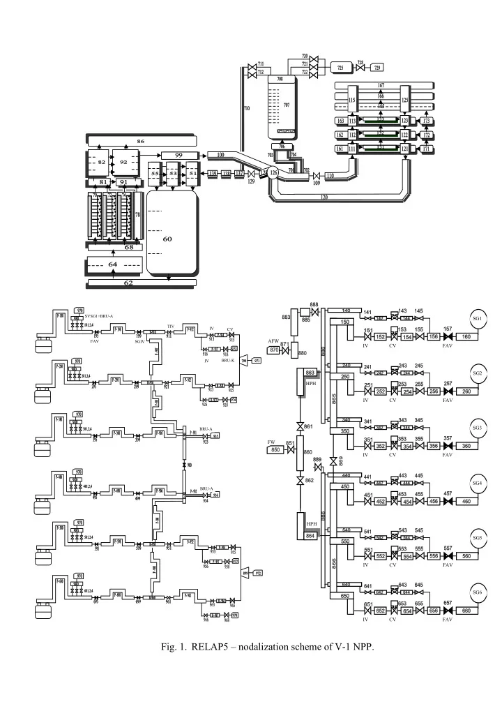

SVSG1+BRU-A SG1 TIV IV CV TG1 AFW FAV SGIV IV CV FAV IV BRU-K SG2 HPH IV CV FAV SG3 BRU-A FW IV CV FAV SG4 BRU-A HPH SG5 IV CV FAV SG6 IV CV FAV Fig. 1. RELAP5 – nodalization scheme of V-1 NPP.
Fig. 2.1. Reactor power. Fig. 2.2. Temperature in hot leg No. 1. EBO V1: Trip RCP - model validation. RELAP5-3D EBO V1: Trip RCP - model validation. RELAP5-3D 120. 330. RELAP RELAP V1 V1 100. 310. Temperature [C] Power [%] 290. 80. 270. 60. 250. 40. -200 -100 0 100 200 300 400 500 -200 -100 0 100 200 300 400 500 Time [s] Time [s] Fig. 2.3. Steam production in SG 3. Fig. 2.4. Pressure in SG 1. EBO V1: Trip RCP - model validation. RELAP5-3D EBO V1: Trip RCP - model validation. RELAP5-3D 600. 4.8 RELAP RELAP V1 V1 500. 4.6 400. Pressure [MPa] Flow [kg/s] 300. 4.4 200. 4.2 100. 0. 4. -200 -100 0 100 200 300 400 500 -200 -100 0 100 200 300 400 500 Time [s] Time [s] Fig. 2. On – transient level validation of the RELAP5 model.
HDV11A-4 throttling HDV orifice HDV11A-41 measurement orifice HDV12A-4 HDV throttling HDV12A-41 orifice HDV21A-4 throttling orifice HDV HDV21A-41 measurement orifice HDV22A-4 HDV throttling HDV22A-41 orifice Fig. 3. Nodalization of the HP injection. 13.5 HDV11-model 13. HDV11-real 12.5 12. Pressure [MPa] 11.5 11. 10.5 10. 9.5 9. 8.5 0 5 10 15 20 25 30 35 Flow [kg/s] Fig. 4. Characteristics of the HP pumps, including discharge line to primary system.
Fig. 5.1. Pressures in primary system and main steam header. Bohunice V-1: "feed&bleed" 1 HP pump 1 relieve valve RELAP5/Mod3.2 14. 12. 10. Pressure [MPa] 8. 6. 4. PRZ 2. MSH 0. 0 1 2 3 4 5 6 7 8 9 10 Time [hours] Fig. 5.2. Collapsed water level in reactor vessel and PRZ. Bohunice V-1: "feed&bleed" 1 HP pump 1 relieve valve RELAP5/Mod3.2 14. 12. 10. 8. Level [m] 6. 4. PRZ 2. reactor 0. 0 1 2 3 4 5 6 7 8 9 10 Time [hours]
Fig. 5.3. Temperatures in reactor vessel. Bohunice V-1: "feed&bleed" 1 HP pump 1 relieve valve RELAP5/Mod3.2 400. inlet outlet 350. saturation Temperature [°C] 300. 250. 200. 150. 0 1 2 3 4 5 6 7 8 9 10 Time [hours] Fig. 5.4. Maximum fuel and cladding temperature. Bohunice V-1: "feed&bleed" 1 HP pump 1 relieve valve RELAP5/Mod3.2 1000. fuel cladding 800. Temperature [°C] 600. 400. 200. 0. 0 1 2 3 4 5 6 7 8 9 10 Time [hours]
Fig. 5.5. Loop mass-flow-rates. Bohunice V-1: "feed&bleed" 1 HP pump 1 relieve valve RELAP5/Mod3.2 500. loop 1 loop 2 400. loop 3 loop 4 loop 5 loop 6 300. Flow [kg/s] 200. 100. 0. 0 1 2 3 4 5 6 7 8 9 10 Time [hours] Fig. 5.6. Mass-flow-rate through PRZ relieve valve. Bohunice V-1: "feed&bleed" 1 HP pump 1 relieve valve RELAP5/Mod3.2 100. relieve valve HP pump 80. 60. Flow [kg/s] 40. 20. 0. 0 1 2 3 4 5 6 7 8 9 10 Time [hours]
Fig. 5.7. Primary and secondary water mass inventories. Bohunice V-1: "feed&bleed" 1 HP pump 1 relieve valve RELAP5/Mod3.2 250. primary secondary 200. 150. Mass [t] 100. 50. 0. 0 1 2 3 4 5 6 7 8 9 10 Time [hours] Fig. 5.8. Collapsed water level in SGs. Bohunice V-1: "feed&bleed" 1 HP pump 1 relieve valve RELAP5/Mod3.2 2.5 SG1 SG2 2. SG3 SG4 SG5 SG6 1.5 Level [m] 1. 0.5 0. 0 1 2 3 4 5 6 7 8 9 10 Time [hours]
Recommend
More recommend