Fatigue Example Andrew Ning December 5, 2016 The figure below shows - PDF document
Fatigue Example Andrew Ning December 5, 2016 The figure below shows a stationary (non-rotating) torsion bar spring statically loaded with a force F = 35 kN, and a torque T that varies from 0 to 8 kN-m. It is simply supported at both ends. The
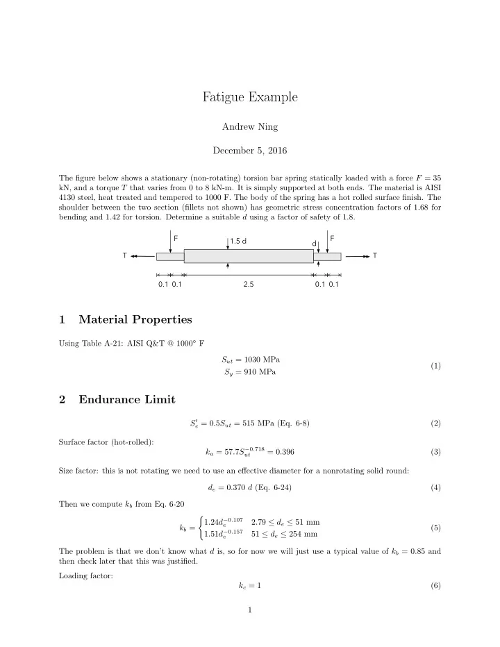
Fatigue Example Andrew Ning December 5, 2016 The figure below shows a stationary (non-rotating) torsion bar spring statically loaded with a force F = 35 kN, and a torque T that varies from 0 to 8 kN-m. It is simply supported at both ends. The material is AISI 4130 steel, heat treated and tempered to 1000 F. The body of the spring has a hot rolled surface finish. The shoulder between the two section (fillets not shown) has geometric stress concentration factors of 1.68 for bending and 1.42 for torsion. Determine a suitable d using a factor of safety of 1.8. F F 1.5 d d T T 0.1 0.1 2.5 0.1 0.1 1 Material Properties Using Table A-21: AISI Q&T @ 1000 ◦ F S ut = 1030 MPa (1) S y = 910 MPa 2 Endurance Limit S ′ e = 0 . 5 S ut = 515 MPa (Eq. 6-8) (2) Surface factor (hot-rolled): k a = 57 . 7 S − 0 . 718 = 0 . 396 (3) ut Size factor: this is not rotating we need to use an effective diameter for a nonrotating solid round: d e = 0 . 370 d (Eq. 6-24) (4) Then we compute k b from Eq. 6-20 � 1 . 24 d − 0 . 107 2 . 79 ≤ d e ≤ 51 mm e k b = (5) 1 . 51 d − 0 . 157 51 ≤ d e ≤ 254 mm e The problem is that we don’t know what d is, so for now we will just use a typical value of k b = 0 . 85 and then check later that this was justified. Loading factor: k c = 1 (6) 1
Remember, that we need to use k c = 1 because we have a combined load situation, and the loading factors we be applied later to the individual alternating loads. Temperature factor: k d = 1 (7) Nothing was said about the operational temperature being anything different than room temperature. Reliability: k e = 1 (8) No mention of a reliability factor. S e = k a k b k c k d k e S ′ e = 173 . 3 MPa (9) 3 Stress Concentration Factors We are given the static stress concentration factors. We don’t know what the geometry is in terms of notch radius, so to be conservative we will just use q = 1, and thus K f = 1 . 68 (bending) and K fs = 1 . 42 (torsion). 4 Compute Stresses Here is the shear and bending (and torsion) diagram: The torque is everywhere constant, and after the first 0.1 m from either end, the bending moment is constant. The critical location will be at the shoulder (location where diameter changes) because that is where there will be a stress concentration. This critical location is marked with a black circle in the figure above. Note that transverse shear stress is very small for beams (unless the beam is stout), so we will ignore it in our calculation. We can also plot how the stress at that critical location varies in time. 2
The bending stress is constant, so it just has a mean value and no alternating component (remembering to apply the stress concentration factor). Note that we use d rather than 1 . 5 d as the side of the shoulder with the smaller diameter will be more critical. Mc M ( d/ 2) 32 M πd 3 = 59893 σ m = K f = K f ( πd 4 / 64) = K f (10) I d 3 σ a = 0 (11) The torsion varies between its min and max Tr T ( d/ 2) 16 M πd 3 = 57856 τ max = K fs J = K fs ( πd 4 / 32) = K f (12) d 3 τ min = 0 (13) Thus, the mean and alternating shear stress is τ m = τ max + τ min = 28928 2 d 3 (14) τ a = τ max − τ min = 28928 2 d 3 The von Mises stress for the mean and alternating stresses separately are: m = 78088 � σ ′ m = σ 2 m + 3 τ 2 (Pa with d in meters) d 3 (15) a = 50105 � σ ′ a = σ 2 a + 3 τ 2 (Pa with d in meters) d 3 5 Check for Infinite Life Using Goodman criteria: σ a + σ m = 1 S e S ut n f (16) 50105 d 3 (1030 × 10 6 ) = 1 78088 d 3 (173 . 3 × 10 6 ) + 1 . 8 Solving for d yields d = . 0869 m = 86 . 9 mm. Let’s check that our assumption on k b was reasonable. Using Eqs. (4) and (5) we find that k b = . 855, which is really close to the value we used previously. We should probably iterate once more, but since it is so close we will just round up d to the nearest size (i.e., d = 90 m). 3
6 Check Number of Cycles for Finite Life Not applicable, because we designed d to be big enough for infinite life (safety factor larger than 1). 7 Check for Yielding S y n y ≈ σ ′ m + σ ′ a (910 × 10 6 ) (17) = 78088 / 0 . 0869 3 + 50105 / 0 . 0869 3 =4 . 66 Design is not critical in yielding, but is governed by fatigue. 4
Recommend


More recommend
Explore More Topics
Stay informed with curated content and fresh updates.